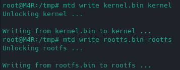
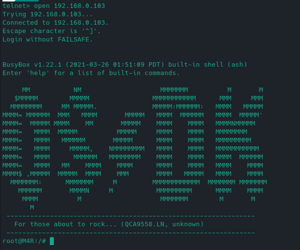
Flashed the firmware successfully from bootloader recovery. Tried telnet and this is where I am at. I'm unsure what to do next.
I haven't done this myself, so this isn't a tutorial but a template for you to think about it yourself.
But this is how I imagine it:
-
chop up the openwrt sysupgrade bin so that you get one file for the kernel and one file for the rootfs
-
in the command prompt you have you use scp or wget to get both of these files over to the device to /tmp
-
use mtd to overwrite the specific partitions in the flash memory with the two files you created in (1)
Here is how mtd is used and even how you compile it static if it isn't present on the firmware you just flashed: https://openwrt.org/docs/techref/mtd
Definitely make sure that you don't overwrite u-boot (in mtd0) or you won't be able to use the recovery anymore.
Thanks for the tips! I'll reply back if I succeed. If I do succeed, I'll post instructions here for other people.
Sorry if I arrived to this party a little late, but I just bought a few of these (M4R v2) and got curious about putting OpenWRT on them. While opening up the device was relatively easy, I made a few pictures to help others to get on the inside:
Usual disclaimer: do this on your own risk...
I suggest using a small flathead screwdriver to push under the inner side of the feet at their middle. There are holes for the screws under them (in my case there were two, your milage may vary). Unscrew them but leave them in the hole. That way the feet remain intact.
TP-Link Deco M4R Bottom: TejtfMh.jpeg (4096×3072) (imgur.com)
The black sidepanel around the ethernet ports is a separate piece. Carefully wedge the screwdriver between the sidepanel and the bottom part.
TP-Link Deco M4R Side panel: YHREszY.jpeg (1997×2297) (imgur.com)
The side panel is held in place by plastic pegs, they should pop off easily. You only need to pop the bottom side of the panel only as much as to allow the ethernet sockets to slide out of their frame.
TP-Link Deco M4R Bottom and panel slides out: u8Mx2jG.jpeg (4128×3096) (imgur.com)
TP-Link Deco M4R Panel Top view 1: Jcxqp2O.jpeg (2885×1809) (imgur.com)
TP-Link Deco M4R Panel Top view 2: tw6tJ6Q.jpeg (3029×1761) (imgur.com)
TP-Link Deco M4R Panel Bottom view 1: b69wAkq.jpeg (3041×1785) (imgur.com)
TP-Link Deco M4R Panel Bottom view 2: lxXhkqc.jpeg (2769×1833) (imgur.com)
Could someone mark the mentioned testpoints/RX/TX on the pictures?
I did make photos many months ago but never got around to editing and posting them because I thought I should write a lengthy explanation too.
Here you have them in an imgur album with explaining text in the description:
About the cables:
TP1 is RX of the router. So you should connect TX of your TTL dongle to it.
TP2 is TX of the router and thus needs to be connected to RX of your TTL dongle.
GND of course needs to be connected to GND of the dongle so both your dongle (and thus PC) and the router share a common ground.
And you never ever connect any Vcc of the dongle and the router with each other. On one hand the router has its own power source and on the other you can definitely damage the SoC if you supply more than 3.3V to it. Further more you don't know what other parts of the router you would be powering via the dongle and that might lead to insufficient power and possibly bricking the device.
Also don't connect a 5V TTL dongle to it. I don't know if the pins attached to TP1 and TP2 are 5V tolerant and neither do you. Definitely test the dongle first with a multimeter.
And after that do you know what you're doing or do you need explanations for that too? Because so far I've only written that to someone who has a bunch of Deco P9 and even a Deco M4R V3, but it's all in German.
Very nice description, thank you. I was only missing the TP1 TP2 locations (I made the pictures in poor lighting conditions and my eyes are not as good as they once were I'm afraid).
I bought my USB-Serial for use with ESP8266-es so they are definitely the 3.3V signal level type, but I never had to use it with a router, as luckily I never bricked one completely. Usually the TFTP recovery methods worked for me up until now.
In this case I plan to use the uboot web recovery first. If I fsck it up, i'll fall back to the serial method. Maybe I should dump the SPI flash just in case...?
The ttl usb dongle I got for my esp8266s is signaling with 5V, which is fine for the esp since it's pins are 5V tolerant, but I wouldn't be so sure about that with the Deco. Definitely test the voltage between TX and GND of the dongle with a multimeter before you use it.
And I'm not sure if I understand the last part correctly. You can't flash OpenWrt via the recovery.
Some updates:
mtd is present in the firmware but I'm stuck on step 1, I can't figure out how to chop up the firmware so I get a kernel and rootfs file. I've tried searching but couldn't figure out what tool I should use. If anyone knows what I should do, please let me know.
I've read multiple times now that you have to cut off some info at the start of the oem image if you want to flash that directly to revert to stock (for other routers of course).
They all use dd for that:
https://linux.die.net/man/1/dd
Here is an example where they cut away the first 0x20200 (that is 131,584 = 257*512) bytes from original firmware:
https://oldwiki.archive.openwrt.org/toh/tp-link/tl-wr1043nd#back.to.original.firmware
With that you should be able to cut out the two different partitions of the sysupgrade image.
Edit:
You might also be able to just write the whole sysupgrade image to "kernel". But no clue if that works.
After some figuring out I managed to cut up the openwrt image file into one kernel and one rootfs file, tried using mtd to write the partitions but it seemingly bricked the router (recovered it using bootloader recovery).
I ran these commands:
cd tmp
curl -LJO https://github.com/bobthebuilder4711/openwrtForDecoM4RV1V2/releases/download/v19.07.8.1/openwrt-ath79-generic-tplink_deco-m4r-v1v2-squashfs-sysupgrade.bin -k
dd if=openwrt-ath79-generic-tplink_deco-m4r-v1v2-squashfs-sysupgrade.bin of=rootfs.bin skip=10240 count=49152 bs=256
dd if=openwrt-ath79-generic-tplink_deco-m4r-v1v2-squashfs-sysupgrade.bin of=kernel.bin skip=2048 count=8192 bs=256
mtd write kernel.bin kernel
mtd write rootfs.bin rootfs
It flashed successfully:

But this left the router bricked. I'm not sure what I did wrong or if the block size I used to calculate the sizes and used in my dd commands were correct or whether I should have outputted them as .bin files.
You do? You can't just use the sysupgrade function?
I tried it but nothing happened, the router restarted back to 19.07.
Your MAC addresses are likely wrong or not working.
In 11-ath10k-caldata you're taking the MAC for 5G wifi out of the "info" partition, which doesn't exist in your .dts.
And in the .dts itself you're using <&uboot 0x1fc00> for eth0, but that's just some MAC every deco bootloader uses and not the MAC on the label on the bottom of your device.
wmac in the .dts doesn't have a MAC address at all.
Could it be that all of them start like this: 12-34-56-...?
This is important because end devices differenciate between different APs (that use the same SSID) by BSSID and that's usually the MAC of the used interface. And I'm guessing that all Decos running your firmware are going to have the same SSIDs.
Also having multiple wired devices with the same MAC in the same network is also going to create problems.
Thank you for your concern, I got my USB dongle from Adafruit for this purpose. It's the blue one with the Profilic PL2303 (I think it's a TA variant), the datasheet states, that the signal levels are 3.3v (CMOS) level not TTL. I think it will not blow up the Deco 
Since last time I have seen your conversation with @KinteLiX and read up on the subject. Am I right to assume that U-Boot is RSA locked? Then for complete support the RSA lock has to be disabled first, before we can flash any unsigned images via U-Boot recovery. Right now flashing anything on the device requires using the "leaked" developer firmware from @origami as it has the required signature and gives access to the device.
Anyway I was away for chistmas and I just got around to get my iron and cables. I will solder the UART tomorrow and try to collect information from serial.
Hi, I have a 21.02 port but the dts file was pretty bad on it (plus some other files), over the last couple of days I've improved it thanks to help from @bobthebuilder.
I've just pushed my latest dts file which has the firmware partition, which should fix sysupgrades (not sure, the verbose option didn't show any info that would help in finding the cause but that may have been it).
I think you still need to do the mtd method if going from 19.07 to mine because 19.07 lacks firmware partition.
From what I read up here our only option would be to find the RSA key, soldering or the leaked fw method. I'm not sure if disabling the RSA check in the bootloader is even possible.
Having a passing familiarity with RSA I doubt we could get the necessary private key to sign our own image (I will check the GPL pack from TP-Link for it, but it would have been a stupid mistake to leave it in there). The different parts of the image (kernel, rootfs, etc.) are individually hashed and signed, and these signatures are checked by U-Boot according to the documentation.
Interesting info, I also doubt you will find it there. In the meantime, I fetched and merged upstream changes (bumped Linux kernel version). I'm gonna use it to compile it and test sysupgrade.
I have found this: U-Boot: Verified RSA Boot on ARM target (denx.de), gives some insight...
Interesting, because RSA uses public and private keys, I wonder if the private key could be extracted from the router because the router's bootloader must check the image somehow, but I could be wrong so don't quote me on that. I don't think it would be legal to share it though.
And if you are already opening the device up and soldering wires to it, you could just flash OpenWrt to it without dealing with extracting keys.
