For the Netgear GS728v2, the package has 16 pins, indeed. But as you say, for the initramfs images, there is no persistent memory defined so far, only the squashfs images use persistent images. And I am not yet ready to flash the Netgear GS728v2, yet, this is my playground for porting the drivers to the RTL839x architecture: as you can see, it boots, the flash driver works, I have even managed to configure VLANs for the up to 52 ports supported, but then I am stuck on getting the Receive DMA working for the CPU-Port 
But I am also not sure that the problem you refer to also applies to the SPI-NOR driver of the RTL838x SoCs. The SoCs are able to directly map NOR flash into memory, they even boot directly from a flash chip, which is mapped into memory at the beginning of the reset vectors of the SoCs on reset. For this strapping pins are used to configure the flash chip, the SoCs do not generally have any ROM that they boot into. Therefore, the NOR driver is very basic and relies on the SoC to do all the work.
First light!
BOOT Loader Version 1.0.0.5 (2019-03-15 17:08:23 UTC)

Board: RTL838x CPU:500MHz LXB:200MHz MEM:300MHz
CPU  : 500 MHz
RAM  : 128 MB
FLASH: 32 MB

Model: GS110TPP
MAC  : 38:94:ED:AE:6D:BC

Hit Esc key to stop autoboot:  1 0
RTL838x# rtk network on
Enable network
Please wait for PHY init-time ...

RTL838x# run loadcmd
Using rtl8380#0 device
TFTP from server 192.168.1.109; our IP address is 192.168.1.10
Filename 'openwrt-rtl838x-netgear_gs110tpp-v1-initramfs-kernel.bin'.
Load address: 0x84f00000
Loading: #################################################################
	 #################################################################
	 #################################################################
	 #################################################
done
Bytes transferred = 3581295 (36a56f hex)
RTL838x# bootm
## Booting kernel from Legacy Image at 84f00000 ...
   Version:      MIPS OpenWrt Linux-5.4.24
   Created:      2020-08-24  10:59:31 UTC
   Data Size:    3581231 Bytes = 3.4 MB
   Checksum ... OK
   Uncompressing ... OK

Starting kernel ...

[    0.000000] Linux version 5.4.24 (build@terra) (gcc version 8.4.0 (OpenWrt GCC 8.4.0 r12805-6ef9db9e1c)) #0 Mon Aug 24 10:59:31 2020
[    0.000000] prom_init called
[    0.000000] RTL838X model is 83806800
[    0.000000] SoC Type: RTL8380
[    0.000000] Kernel command line:
[    0.000000] printk: bootconsole [early0] enabled
[    0.000000] CPU0 revision is: 00019070 (MIPS 4KEc)
[    0.000000] plat_mem_setup called
[    0.000000] MIPS: machine is Netgear GSS110TPP
[    0.000000] Registering _machine_restart
[    0.000000] NO PCI device found
[    0.000000] Initrd not found or empty - disabling initrd
[    0.000000] device_tree_init called


[    0.000000] Using appended Device Tree.
[    0.000000] Primary instruction cache 16kB, VIPT, 4-way, linesize 16 bytes.
[    0.000000] Primary data cache 16kB, 2-way, VIPT, cache aliases, linesize 16 bytes
[    0.000000] Zone ranges:
[    0.000000]   Normal   [mem 0x0000000000000000-0x0000000007ffffff]
[    0.000000] Movable zone start for each node
[    0.000000] Early memory node ranges
[    0.000000]   node   0: [mem 0x0000000000000000-0x0000000007ffffff]
[    0.000000] Initmem setup node 0 [mem 0x0000000000000000-0x0000000007ffffff]
[    0.000000] On node 0 totalpages: 32768
[    0.000000]   Normal zone: 288 pages used for memmap
[    0.000000]   Normal zone: 0 pages reserved
[    0.000000]   Normal zone: 32768 pages, LIFO batch:7
[    0.000000] pcpu-alloc: s0 r0 d32768 u32768 alloc=1*32768
[    0.000000] pcpu-alloc: [0] 0
[    0.000000] Built 1 zonelists, mobility grouping on.  Total pages: 32480
[    0.000000] Kernel command line: console=ttyS0,115200
[    0.000000] Dentry cache hash table entries: 16384 (order: 4, 65536 bytes, linear)
[    0.000000] Inode-cache hash table entries: 8192 (order: 3, 32768 bytes, linear)
[    0.000000] mem auto-init: stack:off, heap alloc:off, heap free:off
[    0.000000] Memory: 117912K/131072K available (4543K kernel code, 157K rwdata, 1000K rodata, 5940K init, 198K bss, 13160K reserved, 0K cma-reserved)
[    0.000000] SLUB: HWalign=32, Order=0-3, MinObjects=0, CPUs=1, Nodes=1
[    0.000000] NR_IRQS: 64
[    0.000000] random: get_random_bytes called from start_kernel+0x32c/0x51c with crng_init=0
[    0.000000] CPU frequency from device tree: 500000000
[    0.000000] CPU Clock: 500 MHz
[    0.000000] PLL control register: efffffff
[    0.000000] Using default baud rate: 38400
[    0.000000] clocksource: MIPS: mask: 0xffffffff max_cycles: 0xffffffff, max_idle_ns: 7645041786 ns
[    0.000016] sched_clock: 32 bits at 250MHz, resolution 4ns, wraps every 8589934590ns
[    0.008635] printk: console [ttyS0] enabled
[    0.008635] printk: console [ttyS0] enabled
[    0.017776] printk: bootconsole [early0] disabled
[    0.017776] printk: bootconsole [early0] disabled
[    0.028241] Calibrating delay loop... 498.89 BogoMIPS (lpj=2494464)
[    0.095209] pid_max: default: 32768 minimum: 301
[    0.100780] Mount-cache hash table entries: 1024 (order: 0, 4096 bytes, linear)
[    0.108907] Mountpoint-cache hash table entries: 1024 (order: 0, 4096 bytes, linear)
[    0.127378] clocksource: jiffies: mask: 0xffffffff max_cycles: 0xffffffff, max_idle_ns: 19112604462750000 ns
[    0.138381] futex hash table entries: 256 (order: -1, 3072 bytes, linear)
[    0.146217] pinctrl core: initialized pinctrl subsystem
[    0.153426] NET: Registered protocol family 16
[    0.226843] clocksource: Switched to clocksource MIPS
[    0.235296] NET: Registered protocol family 2
[    0.241741] tcp_listen_portaddr_hash hash table entries: 512 (order: 0, 4096 bytes, linear)
[    0.251180] TCP established hash table entries: 1024 (order: 0, 4096 bytes, linear)
[    0.259775] TCP bind hash table entries: 1024 (order: 0, 4096 bytes, linear)
[    0.267684] TCP: Hash tables configured (established 1024 bind 1024)
[    0.275281] UDP hash table entries: 256 (order: 0, 4096 bytes, linear)
[    0.282675] UDP-Lite hash table entries: 256 (order: 0, 4096 bytes, linear)
[    0.291091] NET: Registered protocol family 1
[    0.694672] workingset: timestamp_bits=14 max_order=15 bucket_order=1
[    0.718417] squashfs: version 4.0 (2009/01/31) Phillip Lougher
[    0.724886] jffs2: version 2.2 (NAND) (SUMMARY) (ZLIB) (LZMA) (RTIME) (CMODE_PRIORITY) (c) 2001-2006 Red Hat, Inc.
[    0.787390] Probing RTL838X GPIOs
[    0.791089] rtl8231_init
[    0.844017] RTL8231 led function now: ffff
[    0.848595] rtl8231_init done
[    0.959045] Serial: 8250/16550 driver, 2 ports, IRQ sharing disabled
[    0.966366] serial8250: ttyS0 at MMIO 0x0 (irq = 31, base_baud = 12442400) is a 16550A
[    0.977229] b8002100.uart: ttyS1 at MMIO 0xb8002100 (irq = 30, base_baud = 12500000) is a 16550A
[    1.378752] brd: module loaded
[    1.383011] Initializing rtl838x_nor_driver
[    1.387809] Address mode is 4 bytes
[    1.391661] rtl838x_nor_init called
[    1.395517] Flash ID: ffc22019
[    1.401712] rtl838x-nor b8001200.spi: mx25l25635e (32768 Kbytes)
[    1.408550] 7 fixed-partitions partitions found on MTD device rtl838x_nor
[    1.416055] Creating 7 MTD partitions on "rtl838x_nor":
[    1.421919] 0x000000000000-0x0000000e0000 : "u-boot"
[    1.429786] 0x0000000e0000-0x0000000f0000 : "u-boot-env"
[    1.438016] 0x0000000f0000-0x000000100000 : "sysinfo"
[    1.445820] 0x000000100000-0x000000200000 : "jffs2_cfg"
[    1.453992] 0x000000200000-0x000000300000 : "jffs2_log"
[    1.462112] 0x000000300000-0x000001180000 : "runtime1"
[    1.495250] 0x000001180000-0x000002000000 : "runtime2"
[    1.512743] libphy: Fixed MDIO Bus: probed
[    1.517576] Probing RTL838X switch device
[    1.522229] SoC ID: 8380: RTL8380
[    1.525891] Chip version B
[    1.528954] In rtl838x_mdio_probe
[    1.532661] Found compatible MDIO node!
[    1.536955] Deferring probe of mdio bus
[    1.541191] STOPPING Traffic
[    1.645559] Probing RTL838X eth device pdev: 87c6c200, dev: 87c6c210
[    1.666017] Found SoC ID: 8380: RTL8380, family 8380
[    1.671580] rtl8380_init_mac
[    1.674801] Using MAC 000000e04c000000
[    1.678989] In rtl838x_mdio_init
[    1.682902] rtl838x_mdio_reset
[    1.686301] libphy: rtl838x-eth-mdio: probed
[    1.801758] In rtl838x_validate
[    1.805302] In rtl838x_validate
[    1.811643] NET: Registered protocol family 10
[    1.828763] Segment Routing with IPv6
[    1.833034] NET: Registered protocol family 17
[    1.838898] 8021q: 802.1Q VLAN Support v1.8
[    1.844643] Probing RTL838X switch device
[    1.849395] SoC ID: 8380: RTL8380
[    1.853065] Chip version B
[    1.856042] In rtl838x_mdio_probe
[    1.859811] Found compatible MDIO node!
[    1.945863] REATLTEK RTL8218B (internal) rtl838x slave mii-0:08: Detected internal RTL8218B
[    1.956650] Firmware loaded. Size 1184, magic: 83808380
[    4.650303] libphy: rtl838x slave mii: probed
[    4.655221] In rtl838x_mdio_probe done
[    4.667141] rtl838x_setup called
[    4.670758] > 10000001 10000002 10000004 10000008 10000010 10000020 10000040 10000080
[    4.679499] > 1fffffff 1fffffff 10000400 10000800 10001000 10002000 1fffffff 1fffffff
[    4.688221] > 1fffffff 1fffffff 1fffffff 1fffffff 1fffffff 1fffffff 1fffffff 1fffffff
[    4.696939] > 1fffffff 1fffffff 1fffffff 1fffffff     3cff        0        0        0
[    4.705584] CPU_PORT>     3cff
[    5.796874] rtl83xx_enable_phy_polling:             3cff
[    5.802755] Please wait until PHY is settled
[    6.837025] In rtl838x_phylink_validate, port 0
[    6.837547] In rtl838x_phylink_validate, port 0
[    6.852907] rtl838x-eth bb00a300.ethernet eth0: error -22 setting up slave phy
[    6.870695] rtl838x-switch 0.switch: Error registering switch: -22
[    6.877701] rtl838x-switch: probe of 0.switch failed with error -22
[    6.974590] Freeing unused kernel memory: 5940K
[    6.979685] This architecture does not have kernel memory protection.
[    6.986860] Run /init as init process
[    7.158810] init: Console is alive
[    7.177511] init: - preinit -
Illegal instruction
Illegal instruction
Illegal instruction
Illegal instruction
Illegal instruction
Illegal instruction
Illegal instruction
Illegal instruction
rtl838x_set_preinit_iface called
Illegal instruction
[    7.440037] rtl838x_eth_open called 87640c60, ring a7000000
[    7.446215] RESETTING 8380, CPU_PORT 28
[    8.049445] rtl838x-eth bb00a300.ethernet eth0: configuring for fixed/internal link mode
[    8.058423] In rtl838x_mac_config, mode 1
[    8.062850] rtl838x_hw_en_rxtx
[    8.068210] In rtl838x_mac_config, mode 1
[    8.072659] In rtl838x_mac_link_up
[    8.076452] rtl838x-eth bb00a300.ethernet eth0: Link is Up - 1Gbps/Full - flow control off
Illegal instruction
[    8.096985] IPv6: ADDRCONF(NETDEV_CHANGE): eth0: link becomes ready
Illegal instruction
Illegal instruction
Illegal instruction
Illegal instruction
Illegal instruction
Illegal instruction
Illegal instruction
Press the [f] key and hit [enter] to enter failsafe mode
Press the [1], [2], [3] or [4] key and hit [enter] to select the debug level
Illegal instruction
Illegal instruction
Illegal instruction
Illegal instruction
Illegal instruction
Illegal instruction
Illegal instruction
Illegal instruction
Illegal instruction
Illegal instruction
Illegal instruction
Illegal instruction
Illegal instruction
Illegal instruction
[   12.360514] procd: - early -
[   14.490881] procd: - ubus -
[   14.508755] random: ubusd: uninitialized urandom read (4 bytes read)
[   14.548263] random: ubusd: uninitialized urandom read (4 bytes read)
[   14.556139] random: ubusd: uninitialized urandom read (4 bytes read)
[   14.566310] procd: - init -
Please press Enter to activate this console.
[   16.677312] urandom_read: 6 callbacks suppressed
[   16.677327] random: ubusd: uninitialized urandom read (4 bytes read)

Illegal instruction


BusyBox v1.31.1 () built-in shell (ash)

  _______                     ________        __
 |       |.-----.-----.-----.|  |  |  |.----.|  |_
 |   -   ||  _  |  -__|     ||  |  |  ||   _||   _|
 |_______||   __|_____|__|__||________||__|  |____|
          |__| W I R E L E S S   F R E E D O M
 -----------------------------------------------------
 OpenWrt SNAPSHOT, r12805-6ef9db9e1c
 -----------------------------------------------------
Illegal instruction
Illegal instruction
Illegal instruction
Illegal instruction
Illegal instruction
root@(none):/# cd /sys/class/gpio/
Illegal instruction
root@(none):/sys/class/gpio# [   30.698313] random: fast init done
root@(none):/sys/class/gpio# cd gpiochip0
root@(none):/sys/devices/platform/b8003500.gpio-controller/gpio/gpiochip0# cat ngpio
196
Illegal instruction
root@(none):/sys/devices/platform/b8003500.gpio-controller/gpio/gpiochip0# halt
Illegal instruction
root@(none):/sys/devices/platform/b8003500.gpio-controller/gpio/gpiochip0# [  102.138763] reboot: System halted
[  102.142450] System halted.
I did have an issue with the makefile. I added an entry for the gs110 before the gs728, so that they would be in alphabetical order. However, the uImage contained the NETGEAR_KERNEL_MAGIC value set by gs728. When I swapped the order of these two, the output image contained the right uImage magic.
Edit: Fixed by adding NETGEAR_KERNEL_MAGIC to DEVICE_VARS
I forgot to disable the MIPS16 instructions, but (luckily) all I got was "Illegal instruction" notifications. I rebuilt after enabling, but make didn't seem to pick that up. So I'll have to make clean/dirclean, but at least it's booting 
In my prelimary DTS, I've got this indirect-access-bus-id setting, giving me 195 GPIO lines on gpiochip0. Currently going through the list to see what's what. Reset is an active low input on GPIO24. GPIOs 32-63 are all outputs, as are 100-195, although the latter are all set to 0. When toggling 32-63, the lights on the switch ports change, but the mapping doesn't appear to be 1-to-1 with GPIOs.
Let me try to shed some light on this. The RTL838x SoC has several ways of controlling GPIOs, which means mostly Port-Leds for switches with many ports. Currently the GPIO driver does the following mapping:
* 0-31: internal GPIO lines of the SoC via RTL838X_GPIO_PABC_xxx registers
* 32-63, LED control register of the SoC via RTL838X_LED_GLB_CTRL register
* 64-99: external RTL8231 controlled via RTL838X_EXTRA_GPIO_CTRL / RTL838X_EXT_GPIO_INDRT_ACCESS registers
* 100-131: PORT-LED 0 via Serial LED interface of RTL838x, e.g. Green
* 132-163: PORT-LED 1, e.g. Yellow LEDs
* 164-195: PORT-LED 2, e.g. Red LEDs
The RTL838X_GPIO_PABC_xxx registers are not part of the Switch feature block of the RTL838x SoC, but come from a different function block:
#define GPIO_CTRL_REG_BASE		((volatile void *) 0xb8003500)
#define RTL838X_GPIO_PABC_CNR		(GPIO_CTRL_REG_BASE + 0x0)
#define RTL838X_GPIO_PABC_TYPE		(GPIO_CTRL_REG_BASE + 0x04)
#define RTL838X_GPIO_PABC_DIR		(GPIO_CTRL_REG_BASE + 0x8)
#define RTL838X_GPIO_PABC_DATA		(GPIO_CTRL_REG_BASE + 0xc)
#define RTL838X_GPIO_PABC_ISR		(GPIO_CTRL_REG_BASE + 0x10)
#define RTL838X_GPIO_PAB_IMR		(GPIO_CTRL_REG_BASE + 0x14)
#define RTL838X_GPIO_PC_IMR		(GPIO_CTRL_REG_BASE + 0x18)
These pins refer to the GPIO lines of the RTL 838x chips themselves. While there are many, the problem is that the chips only have a handful of such PINs. E.G the RTL8380M has 7 GPIOs, plus one dedicated to the SYS led (GPIO0). Pins are called GPIO1-3, GPIO10-11, GPIO12-14. 7 GPIOs is far too few to power PHYs, read a Reset button and sense things.
RTL838X_LED_GLB_CTRL allows to switch steer the SYS LED, sometimes also the Power Led:
#define RTL8380_LED_GLB_CTRL_ADDR           (0xBB000000 + 0xA000)
  #define RTL8380_LED_GLB_CTRL_BLINK_TIME_SEL_2_OFFSET      (30)
  #define RTL8380_LED_GLB_CTRL_ASIC_CFG_8231_OFFSET         (29)
  #define RTL8380_LED_GLB_CTRL_BUZZER_CMD_OFFSET            (28)
  #define RTL8380_LED_GLB_CTRL_BUZZER_FREQ_SEL_OFFSET       (25)
  #define RTL8380_LED_GLB_CTRL_BUZZER_SEL_OFFSET            (24)
  #define RTL8380_LED_GLB_CTRL_BLINK_TIME_SEL_OFFSET        (22)
  #define RTL8380_LED_GLB_CTRL_EXT_8231_GPIO_EN_2_0_OFFSET  (19)
  #define RTL8380_LED_GLB_CTRL_LED_LOAD_EN_OFFSET           (18)
  #define RTL8380_LED_GLB_CTRL_SYS_LED_MODE_OFFSET          (16)
  #define RTL8380_LED_GLB_CTRL_SYS_LED_EN_OFFSET            (15)
  #define RTL8380_LED_GLB_CTRL_STEP2_PWR_ON_LED_2_0_OFFSET  (12)
  #define RTL8380_LED_GLB_CTRL_STEP1_PWR_ON_LED_2_0_OFFSET   (9)
  #define RTL8380_LED_GLB_CTRL_COMBO_PORT_MODE_OFFSET        (7)
  #define RTL8380_LED_GLB_CTRL_LED_MDC_DUTY_SEL_OFFSET       (6)
  #define RTL8380_LED_GLB_CTRL_P27_24_LED_MASK_SEL_OFFSET    (3)
  #define RTL8380_LED_GLB_CTRL_LED_MASK_SEL_2_0_OFFSET       (0)
So typically you can switch the SYS LED via GPIO 32 + 15 = 47.
To use the serial LED features via a shift register IC, in the DTS the "take_port_leds" option must be set, otherwise they remain under ASIC control, you cannot control them via software. There are more options, then:
if (of_property_read_bool(np, "take-port-leds")) {
		if(of_property_read_u32(np, "leds-per-port", &gpios->leds_per_port))
			gpios->leds_per_port = 2;
		if(of_property_read_u32(np, "led-mode", &gpios->led_mode))
			gpios->led_mode = (0x1ea << 15) | 0x1ea ;
		if(of_property_read_u32(np, "num-leds", &gpios->num_leds))
			gpios->num_leds = 32;
		if(of_property_read_u32(np, "min-led", &gpios->min_led))
			gpios->min_led = 0;
		take_port_leds(gpios);
	}
Frankly a lot of this is not understood, merely configurable 
Kobi
Looking back at the PCB pictures, there are three (non-latching) SN74HC164 8-bit shift registers, and two (latching) SN74LV595A 8-bit shift registers. The traces for the port-speed LEDs (green for GbE, amber for FE) appear to lead to the 74HC164s. The traces for the PoE status (green for PoE+, amber for PoE) would go to the 74LV595s. This would make sense, as these LED groups respectively require 20 (out of 24) and 16 (out of 16) pins to control.
I hadn't implemented take-port-leds yet, I'll give that a shot tomorrow.
For LED software control, have a look at the DTS of the TP-Link T2500g-10TS:
While this works, the issue at the next step is that for a DSA switch there are not the right triggers for the LEDs, see Blink led in different color for 100 or 1000 GBit
As an sidenote: I'll keep track of my changes on github:
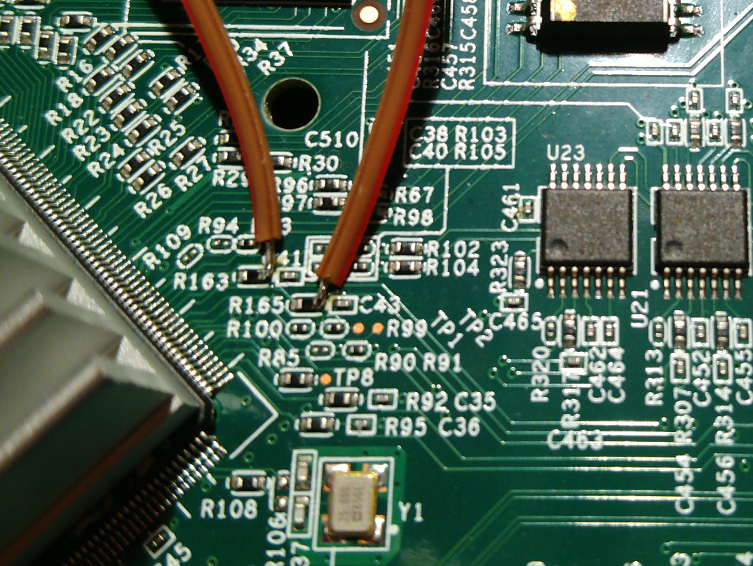
I've added two wires to my board, at R163 and R165, to probe MDIO and MDC. I figured this would be useful, since the other phys seem to require a binary blob, but I can't find this anywhere in Netgear's GPL dump.
This looks like a very exciting project!
I have a GS108Tv2 that uses Broadcom BCM53312. Interesting they moved to Realtek for v3, I suppose all these "web managed" switches use pretty much the same platform.
D-Link's DGS-1210 series has also used three different platforms. I don't know why they do this. Maybe availability of certain parts?
I've purchased three other switches based on the Realtek chips in the mean time, so this little switch hasn't been getting so much attention lately 
Any favorites so far or any models that work with OpenWRT already? I have a Cisco SG250-08 but it takes forever to boot with the stock firmware, the UI and even ssh are very slow and there are so many features that I don't really use it, it sits in its box. All I want is VLANs and some decent security (https, ssh).
Since the GS108Tv3 only has 8 ports, it might be pretty straightforward to add support. For the GS110TPPv1, the missing parts are currently the PoE management and support for ports 9 and 10.
Edit the GS308T (a.k.a. S350 8P) also appears to be Realtek based. It is not PoE powered, so a bit cheaper than the GS108Tv3.
Great to have support for these too. Just a word of caution to those that might be tempted by it, it does NOT have wall mounting holes on the back if that's how you plan to install it. And I believe it has some limited/short warranty that's why it's cheaper than the GS108T otherwise the hardware should be the same.
The GS108T is also built with an RTL8380, while the GS308T appears to be built with something from the RTL93xx-series. I don't think this is quite as well supported currently as the RTL83xx SoCs.
Ah OK. I was going to ask about the cheaper GS108E and similar ones TP-Link TL-SG108 or Zyxel GS1200-8. But these are very likely different boards. These would be attractive for home use due to price, but the software needs a bit of help, e.g. move the management VLAN, have secure https access and disallow crazy configs that make no sense.
U-Boot identifies the GS380T as a RTL838x CPU:500MHz LXB:200MHz MEM:300MHz. What is confusing is the boardmodel is RTL8393M_DEMO. But it appears that is very similar to the situation with the GS108Tv3 as well.
You can read the SoC model (in the u-boot shell) from address the register at 0xBB0000D4. You may have to set the INT_READ_EN bit at 0xBB000058 first to get a useful value from the first register.
Result is 83806800. So this should be an RTL3830M just like the GS108Tv3.
Can any one out there share a close up shot of the electrolytic capacitors on GS110TPP? I need to get new caps.
--- Many thanks. --
Does this picture help? https://biot.com/switches/_detail/wiki/gs110tpp-top.jpg?id=gs110tpp
I could get you the values for C320 and C335 later, if you can't recover them from you device.