Be sure to never connect a power source to this Vcc pin of the serial connector (which is unnecessary anyway). I did by accident with the USB 5V supply. This broke my MR33. The LED stayed dark, and in fact I got a short circuit between pin 1 (Vcc, normally 3.3V) and pin 4 (ground) of the serial connector on the board.
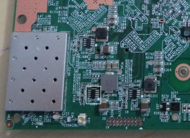
I investigated the issue and found that the short circuit was made by U26. U26 is tagged AEUH which means that this is a MP2233DJ DC-DC converter made by Monolithic Power Systems. With some SMD reworking skills and some luck to find a supplier for a single piece, you can replace the circuit. I got the MR33 back up and running this way.
You absolutely never want to connect to the Vcc pin when using UART, only time you want to do so is if you are connecting and powering some sensor over UART.
Otherwise you can get some nasty ground difference and fry your board
DO NOT under any circumstance connect the live pin (the 3.3 or 5V one) to your USB-TTL dongle as that could damage the dongle. It's not required in any dongle as they are USB-powered anyway and can auto-sense the data voltage.
WARNING!: Some people reported they fried their router connecting the voltage pins spite it isn't neccesary. NEVER connect voltage pins when using USB adapters unless you know what are you doing. Unless you need to power the device, you don't have to connect the voltage pins. And you usually don't need to power it this way - use the router power supply.
good. maybe also useful in the Flashing Instructions for the MR33.pdf on google drive. it states on p.5, Setting up serial connection: Pin 1 Vcc (3.3V - Optional). I'd suggest 3.3V - Don't connect
what's going on here is that not everybody uses usb-to-tll/cmos cables. The oldskool RS232-to-tll/cmos converter based on the MAX3232 need the VCC/3v3 pin connected. Otherwise the MAX3232 chip is not powered and there will be nothing on the console/serial.
@frtz
Hey, can I have your permission to add your post to the MR33.pdf? (Please let me know what attribution I should use. I.e: Do you want to remain anonymous or if I should do the "full name" + link to your profile/website etc.)
@frtz is there a way to verify/test that it is U26 that is fried? My USB-to-TTL cable specifically said to be 3.3V but fried the MR33 anyway Got some MP2233DJ on the way but they will take a moment to arrive. Maybe i can verify the short by testing some leads on the chip?
Putting 5 volts onto the 3.3 volt supply bus could potentially burn out any or all of the chips running on 3.3 volts, which is most of them in the router.
On my board I got a sort of short circuit between the Vcc pin and ground (well less than 1 Ohm). @mk24 this probably protected the other 3.3V chips. I found the culprit (U26) by connecting a low voltage source delivering about 1A to the Vcc pin and then scanning the temperature of the board using an infrared thermometer. U26 and the associated inductor were a couple of degrees C hotter than the rest of the board. I removed U26 and the short circuit went away. Then I reconnected the MR33 power supply and simultaneously sent 3.3 V from an external power supply to the MR33 Vcc pin, and the MR33 LEDs came up again like before. After the MP2233DJ replacement my MR33 has been working ever since.
@frtz thanks for the input! So far i have confirmed to also have the short between Vcc and GND on the serial, which did go away after unsoldering the MP2233DJ. The MP2233DJ in question shorts between pin 3 and 4 which are SW (Switch output) and GND, a fresh MP2233DJ does not ( which makes sense i guess ) instead showing a resistance of 500Ohms. I have not gotten around to soldering the new one in but i will report on it once done.
 Got some MP2233DJ on the way but they will take a moment to arrive. Maybe i can verify the short by testing some leads on the chip?
 ) instead showing a resistance of 500Ohms. I have not gotten around to soldering the new one in but i will report on it once done.
 ( old hard drives have a bunch )