Maxwell HaasMesh documentation for OpenWrt beginners

Following this conversation, it occurs to me that the Maxwell HaasMesh project might be a vector into OpenWRT for some people with little to no previous experience with OpenWRT, let alone the mesh code sitting on top of it & the OpenWRT config needed to support it, and how to expand that configuration for adjacent needs.

So I propose a dialog with Andy @drandyhaas and others familiar with it, so that I and others can perhaps add to the project's documentation in this Gdoc.

I'll start :slight_smile:

What is the purpose of each of these 3 extra interfaces?
In which config file(s) are they configured?

Good idea!
I've made a copy of the documentation, editable by all, here:

1 Like

These extra interfaces are for the mesh between router nodes. They use the "batman" kernel network drivers. Some info is here:

bat0 is the main interface master for the mesh. All data to/from the mesh from this router goes through bat0. It is then bridged to the br-lan (LAN) master interface, so it's connected to the other LAN ethernet ports on the router and the wifi access points on the router.

bat_eth is the ethernet backhaul interface. It's a slave of bat0. There will be one of these interfaces for each ethernet backhaul port on the router.

bat_mesh0 is the mesh wifi interface. It is also a slave of bat0. All mesh wifi traffic to/from the device goes through this interface.

All interfaces are specified in /etc/config/network.

Heya Andy,

A few background questions:

  1. Maxwell’s default config appears to have the ‘HaasMeshWifi’ BSSID bonded to both 5GHz radios, but the 'HaasMesh' BSSID is bonded to only one of the 5GHz radios, is this correct? But doesn’t that mean, if a device inadvertently connects to the ‘dual-use' radio, it will be sharing that radio’s bandwidth with Mesh traffic (both its own forwarded traffic, as well as other users' traffic)? (i.e. half-or-less of the radio’s thruput, all other things being equal). If I'm correct, why do this, what's the benefit compared to dedicating one radio to HaasMesh?

  2. When you add a node to an existing network, is it possible to transfer all the config from the hub-node, or any other to the new node? Or does this simply come down to saving configuration files & restoring them as needed?

Anthony.

Thanks for the thoughtful questions!

  1. Yes, if the client chooses to bond on the ch149 it would share bandwidth with the mesh (unless there is Ethernet backhaul). But the client usually is smart enough to bond to the channel that has less interference. If there were other interference on ch36 you want to have ch149 available to the client. If you want to experiment, you can disable ch149 via a button on the wireless interfaces webpage on each node.

  2. The only things that could or should be synced to a new node that joins are the ap ssid/pw and the root login pw. That could be automated, but it is also pretty simple to just update them from the hub page when you are done adding nodes.

ok, let's chat about VLANs for a bit.

first, only the hub does routing, right? it's just that a single standard router config is duplicated to all mesh nodes, and then on the mesh-hub the LAN i/f is configured to point to the gateway IP on the WAN, whereas all mesh nodes have their LAN gateway IP set to the mesh hub (192.168.2.1 by default), right?

next, attached here is a screenshot from one of several youtube videos I've been using to wrap my head around VLANs (I understand the concept, it's getting the 'orientation' of off vs tagged vs untagged terminology clear in my head, as well as the difference between a Default VLAN and a Native VLAN, and whether either of those has any relevance here):

So this guy's Switch config screen shows 2 VLANs, 1 & 2, for LAN & WAN respectively. His also shows 'CPU(eth1)' (i.e. for CPU//WAN traffic) and 'WAN' physical ethernet port.

But Maxwell's config *doesn'*t show CPU(eth1) nor WAN interfaces. Why is that?

But there's still 2 VLANs shown... I think VLAN 101 is for LAN traffic... but what is VLAN 102 for? in /etc/config/network there's:

config interface 'bat_eth'
	option mtu '1600'
	option proto 'batadv_hardif'
	option master 'bat0'
	option ifname 'eth0.102'
	option macaddr '00:23:03:67:64:CC'

...which I think means the physical ethernet (lan, not mesh backhaul) ports are on VLAN 102, it's only for them?

...which I think means there is no VLAN for mesh traffic? (that's all contained within the Bat trio?)

| Anthony May techydude
August 21 |

  • | - |

ok, let's chat about VLANs for a bit.

first, only the hub does routing, right? it's just that a single standard router config is duplicated to all mesh nodes, and then on the mesh-hub the LAN i/f is configured to point to the gateway IP on the WAN, whereas all mesh nodes have their LAN gateway IP set to the mesh hub (192.168.2.1 by default), right?

Yes. Basically the whole 192.168.2.x subnet is like all nodes are plugged into a single hub. But there is routing of packets by "batman" that cleverly figures out how to get to/from each node to/from other nodes.

next, attached here is a screenshot from one of several youtube videos I've been using to wrap my head around VLANs (I understand the concept, it's getting the 'orientation' of off vs tagged vs untagged terminology clear in my head, as well as the difference between a Default VLAN and a Native VLAN, and whether either of those has any relevance here):

So this guy's Switch config screen shows 2 VLANs, 1 & 2, for LAN & WAN respectively. His also shows 'CPU(eth1)' (i.e. for CPU//WAN traffic) and 'WAN' physical ethernet port.

But Maxwell's config *doesn'*t show CPU(eth1) nor WAN interfaces. Why is that?

How this shows up on the switch page or network interfaces page depends on the hardware setup as well as the software/drivers in the kernel. There's been effort to standardize it in openwrt rel 21 and modern DSA drivers.

But there's still 2 VLANs shown... I think VLAN 101 is for LAN traffic... but what is VLAN 102 for? in /etc/config/network there's:

config interface 'bat_eth'
	option mtu '1600'
	option proto 'batadv_hardif'
	option master 'bat0'
	option ifname 'eth0.102'
	option macaddr '00:23:03:67:64:CC'

...which I think means the physical ethernet (lan, not mesh backhaul) ports are on VLAN 102, it's only for them?

...which I think means there is no VLAN for mesh traffic? (that's all contained within the Bat trio?)

The 101 is for lan Ethernet. That vlan is directly bridged to the bat0 and wifi ap interfaces.
The 102 is for Ethernet backhaul of mesh traffic. It is owned by bat0.

d'oh! i completely missed the bat_ in the interface name :wink:

ok, i need to change gear on the questions for a bit; i've just moved into a house of the kind that I anticipated moving into when I first backed Maxwell on CrowdSupply last December, a thick brick/concrete home in Portugal, and 5GHz doesn't travel well in here :-(, the upstairs node #3, 192.168.2.3) doesn't connect to either of the other nodes.

So I brought it back downstairs in relatively close range to try changing channels, to see if I had better luck.

I changed all 3 nodes from Ch149 to Ch100, then applied the changes to all 3 in rapid sequence. But that seemed to break the mesh connections, even though there were now in easy wireless range; I'd remain wirelessly connected to the hub (which I was closest to) sometimes, but neither of the other nodes would show up (unless I connected Ethernet cables), and sometimes it seemed like the laptop would connect to one of the other AP nodes and of course not get an IP from DHCP...

So I reconnected Ethernet & changed to Ch132, same problem. There was lots of rebooting and connecting/disconnecting Ethernet cables, all to no avail.

So I changed all 3 back to Ch149 and bingo, mesh immediately reconnected between all 3 nodes.

What am I missing? Can the mesh not be set to any channel (the same channel for all nodes, right?)

P.S. I'm still on " Powered by LuCI openwrt-19.07 branch (git-20.247.75781-0d0ab01) / OpenWrt 19.07.4 r11208-ce6496d796", as that's what came with the routers, and I haven't worked out how to build the newer firmware, which I can see in Github is somewhat newer... is this causing me problems?

Also, Ch149 has a max tx power of 13 dBm / 19mW (at least it does here in .pt), which is pretty low compared to the allowed power on lower Channels...

For getting through thick walls, if there's any way to get an ethernet cable around or through (out a window and in another?), use ethernet backhaul - it's far superior. You could also switch the mesh to use 2.4 GHz, and pinning the 2.4 GHz to a fixed channel - of course you then get a max of ~50 Mbps, but that may be better than nothing.

Ch100 may not work on all hardware. And it depends on the "country code" selected for the wifi driver.

There's no real improvements relevant to these issues in more recent builds/firmware.

The power of Ch149 is limited by the hardware and country code. In the US I am getting a full 1W (30dB).

HaasMesh is awesome! It's exactly what I needed for my Archer C7s spread around my house. I really like the network map and the automated way for adding new nodes.

I just have one question, what would be the proper way for adding Guest WiFi to HaasMesh? Is there a plan to add it natively to HaasMesh?

Thank you

Omar

I'm glad you like it!
If you mean adding an additional ssid, on each node, it can be easily done by hand by just duplicating the existing entries in /etc/config/wireless. And that would be easy to automate from the monitor page.
If you mean in addition isolating the traffic on that guest network so that they can not see clients on the original ssid, it's more complicated. I don't know how to do that at the moment, though I know it's possible.

That's actually the topic of my next msg!

I want to setup 2 extra VLANs with associated SSID for Guests & IoT stuff, to achieve isolation from each other & the 'main' lan, with the IOT lan having no internet access (assuming you're doing a 'home brew' IOT setup, like with Home Assistant et. al., rather than one of the cloud-based platforms (Amazon/Google/Apple/etc), and with the Guest zone having no access to the router (and specific rules to allow only certain exception traffic between them).

From the reading/watching I've done, this is the broad-brush set of steps, but i've a few questions, & unsure about the sequence of performing these additional configs:

  1. create 2 new Firewall Zones: (eg. ‘Guest-Zone’ & ‘IOT-Zone’) with accept/reject/forward settings as appropriate to their use-case

  2. create 2 new VLANs for the new Guest & IOT lans,

  3. create 2 new Interfaces, ‘Guest-if’ & ‘IOT-if’, with ‘bridge interfaces’ enabled, specify subnets (eg. 192.168.3.0/24 & 192.168.4.0/24), & enable a DHCP server for each i/f. Assign each new i/f to its matching Firewall Zone (as defined above), and bound to these Interfaces:

    • Ethernet BAT0
    • the respective new VLANs created above
    • any new WLANs configured below (i guess you have to come back to this after you've created them? or do step-4 before this step?)
  4. add WLAN interfaces: add SSIDs for ‘Guest’ & ‘IOT’ to each physical radio, then assign each to the appropriate newly created Networks

AFAIunderstand, this config needs to be replicated on all mesh nodes, because this is all Layer2+Layer3 configuration on the LAN-side, right?

I think due to the deliberate isolation between the VLANs, I'll need to add routing rules for DNS & DHCP to access those router services.

If I've groked your replies above, Andy, the binding of the 2 new interfaces to both the Eth BAT0 and the new VLANs should give me what I want, but I'm not sure. I'll probably try this over the weekend (after I've installed a long eth cable to upstairs :wink:

Hey @drandyhaas , separate to the above, I've run a Cat7 eth cable between the mesh hub & the node upstairs, so that's helping a lot (although I did manage to get 150-250 Mbps between all the nodes, despite the multiple thick walls, albeit at the expense of local tx power compliance, which was cromulent for clients to access the internet, but not sufficient to be able to relocate the NASs upstairs.

But when I ran the 'Bandwidth between me and nodes' tool, i'm only getting a curiously inconsistent 400-550 Mbps between the node & hub (which are eth wired). This at first surprised me, that I wasn't getting at/near wire speed.

Then I remembered that the mesh backhaul network is software-routed via BATMAN, right? It's not being offloaded to Switch hardware?

Right, it's certainly going through the CPU. 500Mbps is typical for the the ea8300. The CPUs also have to generate and receive all the packets for iperf3. So just routing packets will be better than the iperf3 numbers.
My new wifi6 Maxwell unit..

gets near wired speed for backhaul, and faster wifi!

1 Like

Hey Andy,

I like to make diagrams of things like this, to understand the structure of what's going on, at least when a 2d diagram makes sense.

For the sake of diagramatic simplicity, I've not shown that radio1 is configured by default to have both the mesh & wlan SSIDs attached to it, only mesh.

q1: how close is this to reality? is this the right way to show that BATMAN is that virtual/pan-node interface carrying all traffic as though it were all on a single device?

q2: my aim is to add 2 additional networks (192.168.3.0/24 and .4.0/24) for Guest and IOTlan, with separate firewall zones, and add SSIDs to radio(s) as required. Can BATMAN on bat0 handle traffic for multiple networks? Or does 'bat0' need to be replicated for each network (i.e. bat1, bat2)?

i forgot to @ mention you in my last msg, @drandyhaas , ICYMI. and I updated the pic after the OP, too.

very open to feedback on the usefulness of a diagram like this to the Maxwell documentation. things get a bit more complicated to depict diagramatically when you add extra firewall zones, networks, etc.

i had success last night implementing a new firewall zone, interface, & wlan for the guest, on the hub router. i'll try adding the same config to my other 2 nodes tonight.

i subsequently read a little of the BATMAN stuff and realised it's layer-2, and so it's promising to be really easy to setup the isolated additional guest and iot "VLAN"s, but AFAICT they're not being implemented with VLANs, I haven't had to touch the VLAN config, it all seems to be done 'automagically' by BATMAN, which is pretty cool!

The diagram is nice! I'll let others comment on the usefulness.
I will maybe have some time next week to look into the guest network thing. But yes, batman is layer 2, so I think the idea is you simply use it to define different network segments. I haven't looked into how that's done yet - it sounds like you have a bit, so please share.

So tonight wasn't as successful as last night, to say the least.

Last night, entirely and only on the mesh HUB router, I added a Guest firewall zone, extra 'GUEST' interface (192.168.3.0/24) bound to 'bat0', and a couple of guest SSIDs (on the 2.4 & 5 GHz radios 0 & 2). Worked like a charm. I even had .3.0's DHCP telling clients to use my two pi-holes on the 'lan' .2.0 network for DNS, with a routing rule to allow .3.0 clients to access those two .2.0 DNS server IPs (only port 67 & 68). Perfect.

But replicating this config to the 2 mesh nodes was a complete failure.

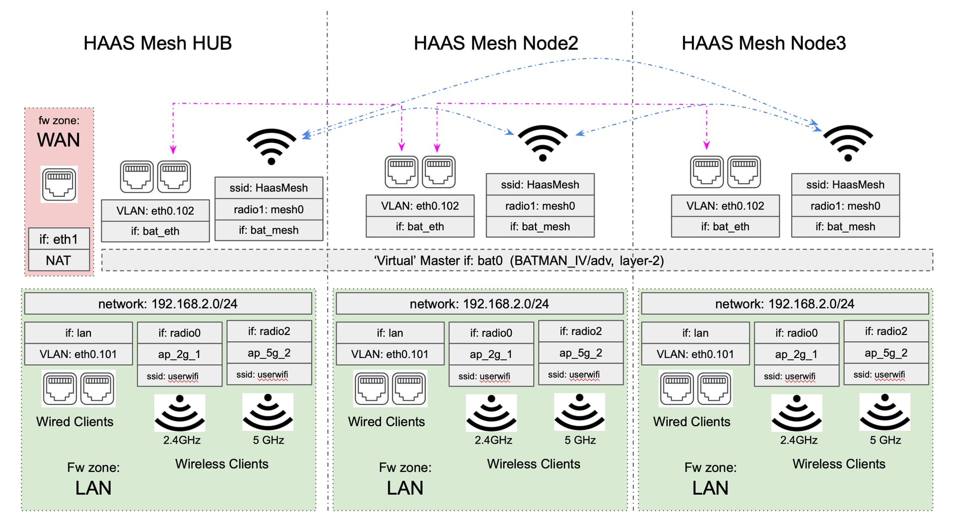
(Background: Although 192.168.2.1 is the Hub in your terminology, I still consider it a node too, so i refer to 192.168.2.2 as node-2, and 192.168.2.3 as 'node-3'. My node-2 is wireless mesh backhaul only (on radio1 which is dedicated to mesh), and node-3 upstairs is wired, though all 3 get at least some degree of connectivity via the wireless mesh; (this is presumably not used for comms between wired nodes?).

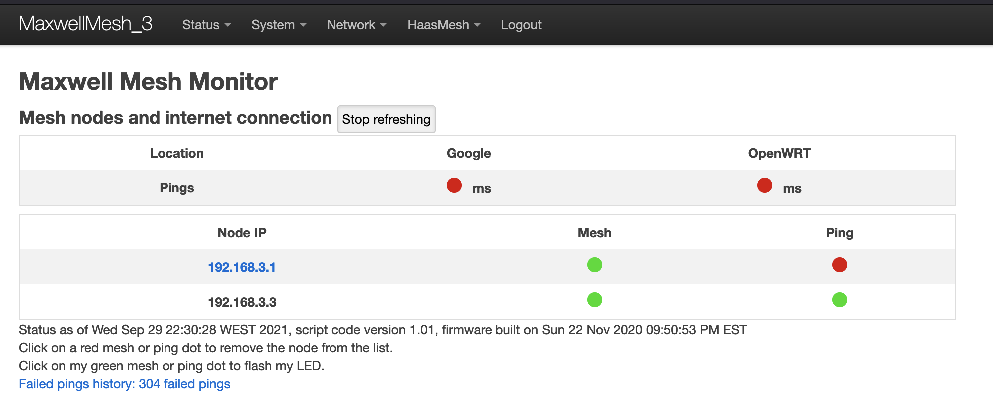
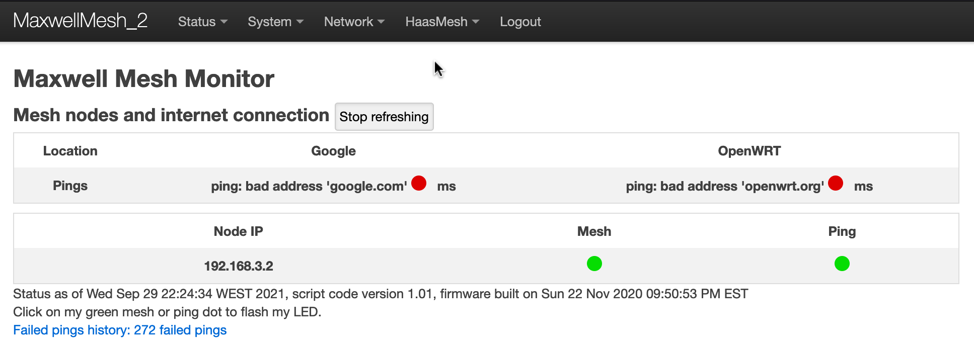
On both nodes 2 & 3, I can add the Guest firewall zone, create the .3.0 interface, create the Guest SSIDs bound to the new Guest .3.0/24 interface, but then when I add the 'bat0' binding to the Guest interface, the mesh seems to fail. Exactly how it fails I'm not really sure at all. But there's a hint in the HaasMesh Monitor page for node-3, which is now showing the IP address of the guest (192.168.3.0/24) for mesh connectivity, instead of .2.0/24:

To clarify, the wired node-3 Monitor page is showing .3.1 (hub) and .3.3 (itself), but node-2 (wireless) is not present.

I had to plug an ethernet cable into all 3 devices, with laptop set to static .2.x IP (DHCP wasn't working), and unbind the Guest 192.168.3.0/24 interface from 'bat0', then reboot, to get back to scratch.

I'm pretty much out of ideas at this stage. In a standard openwrt setup, VLANs would be added for the additional networks (guest .3.0/24, etc) and can be carried over a single ethernet to remote APs. But I've no idea if that is necessary, or would work, or break things even more, under BATMAN...

@drandyhaas Here's what node-2, the node with wireless-only connectivity, showed after the Guest interface was bound to 'bat0' (& i could only see this connected via ethernet with a static IP, because DHCP on the hub wasn't accessible):