I have got two routers. One for DSL(slow, dualstack) and one for Cable(fast, ds-lite) Internet.
DSL: AVM Fritzbox 7490
slow
vpn server to connect to the lan
low ping
Cable: Noname by ISP
fast
high ping
I have bought a third router (Linksys WRT3200acm). Now I want to use it to load balance between the other routers. But I want to place it freely in my LAN to have another WiFi AP.
Also the cable router is in another room. All routers are connected over switches.
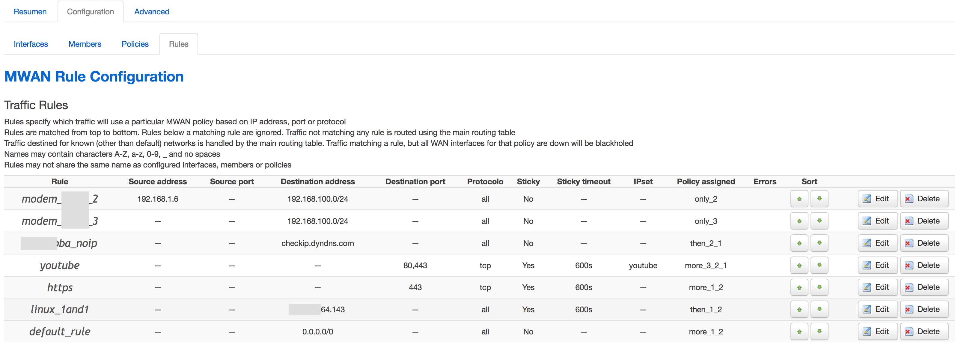
Currently I only found following tool in openwrt: https://wiki.openwrt.org/doc/howto/mwan3 It seems to only work when the third router is placed directly behind the other two.
Is it possible to use mwan3 to load balance between the gateways?
The easiest way is to use Luci, but if you post your uci show network|grep switch output and try also swconfig list it will say probably dev switch0 so swconfig dev switch0 show should give us a complete verbose output.
On the switch we need to remove a LAN port from the LAN network and add it to a new switch instance that will be linking that port to a new vlan... then you could create a new network interface and add that vlan to it.
On luci you can also do it, on Network - Switch you will see a table, check desired LAN port plugging and unplugging an ethernet cable conected to some computer or network device, and you will see the status icon change from "no link" to the speed detected. set that port off on all rows, and add a new row to the table.
you must set now that port to untagged on that new row, and the CPU port (set as tagged on the other rows) must set also to tagged...
That means that the port will be a normal network port (untagged) and the CPU will have tagging so it will be able to identify it.
If you put a port as tagged then that vlan must be tagged also on other devices in order to read data packets, that is for having to different networks on a same cable (we don't need that here).
Post either a screenshot of luci or the commands output and I will try to help.
It shouldn't be connected on that ports. If I would connect those ports, I would need to connect it to a switch to the same network as port 6. This won't work.
The other 2 routers are in the same network (over a switch), with no support of vlan. Also I cannot directly connect them to the lede router.
To make this work with one cable, the equipment on both ends of the cable has to support VLAN tagging, so you can combine the networks (two "raw" links to the ISP modems, and your LAN) and split them up again within the WRT3200.
The thing I don't get here is that you want to load balance which implies to me that you want someone on your LAN to be able to say in their browser connect to say http://www.google.com and then you want your equipment to decide to either send this connection via ISP1 or via ISP2 based on something about how congested the links are. Is that right?
If that is right, I have to ask whether your LAN has public IP addresses, and/or public IPv6 addresses. If not, then you'll need to NAT on both links, if so, you'll need to figure out whether you're having ISP1 carry traffic for you even though it's part of ISP2 public network or not... and vice versa. This seems very non-trivial.
Perhaps you can explain more about what you're trying to achieve.
Many modern "dumb" switches will pass tagged VLAN packets just fine, especially if they have jumbo frame ability. So if you need a few more ports, a dumb switch may be fine. But you're going to need your routers to tag the packets.
I have got two ISP with public ip addresses (one for each). Each one in a different physical location in my house )one router for each). I want to use both, depending on the load.
BUT I cannot directly connect them to my wrt. There are switches in between.
With direct connection it would work as suggested by briaian87b.
The SG108E looks like it would do the job but I don't actually own one so I'm not endorsing it. Note that there is also a SG108 without the E which costs slightly less but is just a dumb switch.
Load balancing works great with two lines of equal speed. I don't know how it works when one is much faster. Usually then you would use the fast one for all traffic and "fail over" to the slow one if the fast line service goes down.
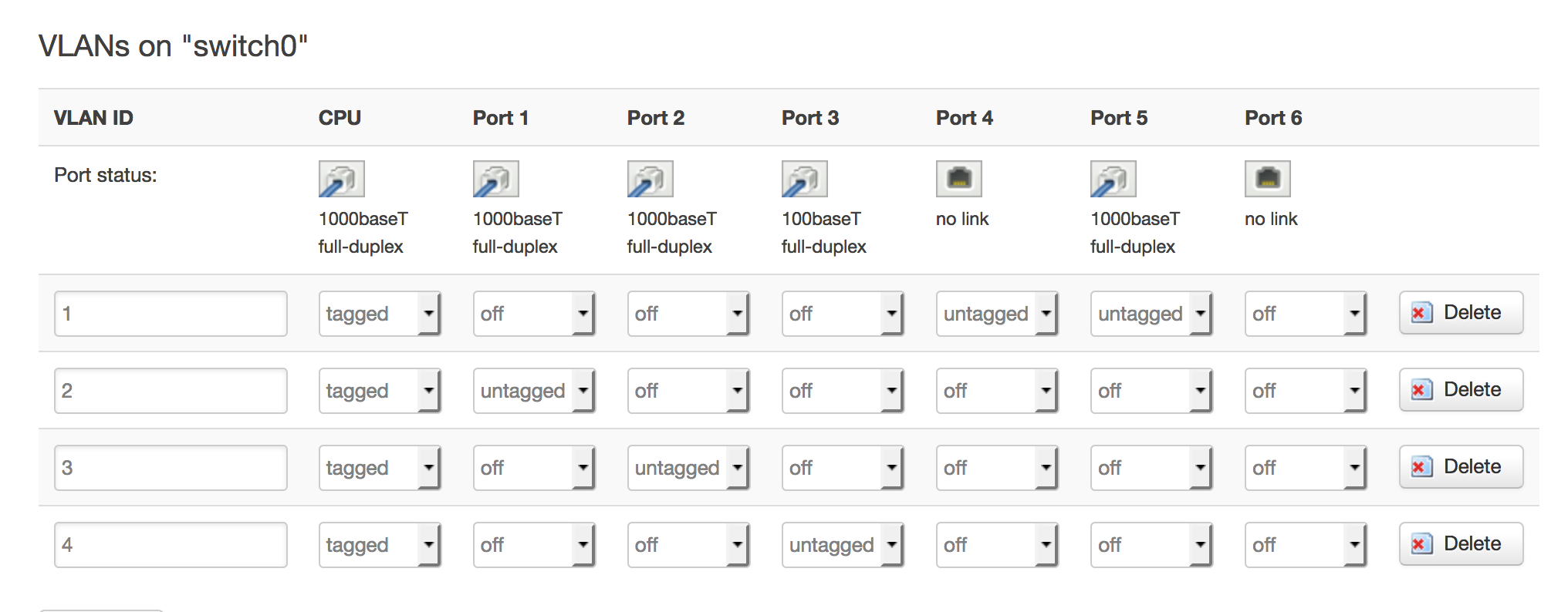
Ports 5 + 6 are the eth0 / eth1
Port 4 is my old WAN port
The untagged ports are used for my normal network.
Now I connected my old WAN port (VLAN2) with a LAN port of VLAN1.
On VLAN 1 I have created an interface for my normal network on eth0.1
Gateway is its own IP
On VLAN 2 I have created 2 interfaces (eth0.2 / eth1.2) with their own MAC and IP.
Each Interfaces gets the gateway of one of the other Internet Routers. Firewall is set to WAN.
Now it is working fine.
Is it possible to connect VLAN 1/2 internal by software so I don't need the the cable loop to connect my old WAN to the LAN port?
I don't understand, my notes work just fine...
If you plug a modem (or router with different subnet than the OpenWrt) to existing wan port, and you configure one of the LAN physical ports to act as a new vlan and add it to a new network and in that physical port you connect another modem (or router with different subnet than the OpenWrt) it should work just fine, there is no need to use a cable loop.
Sample config (you will have something like this at the end) currently working on a TP-Link WDR4300:
network.lan=interface
network.lan.force_link='1'
network.lan.type='bridge'
network.lan.proto='static'
network.lan.netmask='255.255.255.0'
network.lan.ip6assign='60'
network.lan.ifname='eth0.1'
network.lan.ipaddr='192.168.1.1'
network.wan=interface
network.wan.ifname='eth0.2'
network.wan.peerdns='0'
network.wan.metric='10' # this was added
network.wan.proto='dhcp'
network.@switch[0]=switch
network.@switch[0].name='switch0'
network.@switch[0].reset='1'
network.@switch[0].enable_vlan='1'
network.@switch[0].mirror_source_port='0'
network.@switch[0].mirror_monitor_port='0'
network.@switch_vlan[0]=switch_vlan
network.@switch_vlan[0].device='switch0'
network.@switch_vlan[0].vlan='1'
network.@switch_vlan[0].vid='1'
# 0 is CPU, 1 is WAN, 2-3-4-5 are the four LAN ports, 6 is inexistant.
#network.@switch_vlan[0].ports='0t 2 3 4 5' # this was previous
network.@switch_vlan[0].ports='0t 4 5' # was modified to this
network.@switch_vlan[1]=switch_vlan
network.@switch_vlan[1].device='switch0'
network.@switch_vlan[1].vlan='2'
network.@switch_vlan[1].ports='0t 1'
network.@switch_vlan[1].vid='2'
# from this to below lines were added:
network.@switch_vlan[2]=switch_vlan
network.@switch_vlan[2].device='switch0'
network.@switch_vlan[2].vlan='3'
network.@switch_vlan[2].vid='3'
network.@switch_vlan[2].ports='0t 2'
network.wan2=interface
network.wan2.ifname='eth0.3'
network.wan2.proto='dhcp'
network.wan2.metric='20'
network.wan2.peerdns='0' # to force to use the below DNS's
network.wan2.dns='8.8.8.8 8.8.4.4 208.67.220.220 208.67.222.222'
network.@switch_vlan[3]=switch_vlan
network.@switch_vlan[3].device='switch0'
network.@switch_vlan[3].vlan='4'
network.@switch_vlan[3].vid='4'
network.@switch_vlan[3].ports='0t 3'
network.wan3=interface
network.wan3.ifname='eth0.4'
network.wan3.proto='dhcp'
network.wan3.metric='30'
network.wan2.peerdns='0' # to force to use the below DNS's
network.wan2.dns='8.8.8.8 8.8.4.4 208.67.220.220 208.67.222.222'
network.wan3.macaddr='a0:f3:27:43:34:c1' # optionally you can set fake macaddr to change and release-renew the iface to get new IP on cablemodem
The main difference to my setup is that I don't have a direct cable connection to my routers. There connected to my network. The cable loop is quite the same as the direct connection to wan on your setup.
Ahhh, Ok, I understand now... yes, you will have to had that cable if you dont have near the modem you could configure two ip's on same iface too, each ip config will connect to each gateway ... but you will have problems with the interface configuration later... so avoid that trouble.
I guess the only workin setup is to make the new Netgear the main route, DHCP and DNS for every device in your house. Otherwise you cannot do actual load balancing.
The respective LAN ports of both of your existing routers need to become WAN ports for your Netgear.
If you want to have 3 AP devices in your network, however, they need to stay LAN of your network.
My suggestion:
Make sure your existing routers span individual subnets.
Disable DHCP servers on both of your existing routers.
Just wire a LAN port of each of your existing routers to your Netgear.
Create two distinct interfaces on your Netgear, both on eth0.2 (so the router expects both to be plugged into the same vlan segment), both of type static. Make sure one is in IP range of your slow Uplink and the other one in IP range ofnthe fast Uplink.
Now use those new interfaces as source for mean
That, imho, is the only way you can use your existing routers both as uplink one one hand and keep their AP feature intact on the other.
Adding a couple of vlan aware switches somewhere won't help at all. You would have to make vlan decisions not on the wire but within your existing routers (meaning: Both, LAN and WAN would need to leave the existing routers either on individual ports untagged or on a common port tagged) which is not possible with original firmwares of your existing routers.
As for the TP-Link vlan switch: stay away. I have two of those, they are crap. Management can only be done on vlan1. Vlan 1 is always assigned to all ports (so you cannot unassige it), which results in management being always possible on all ports. And there's no web ui but only a windows-only Java client. So it's useless in terms of security and unmanageable on Linux and OS-x. As long as you only want to separate home use IPTV that's probably enough, but for everything beyond that just not enough.
Perhaps in older versions but this is not true with the current v3. There is a web management interface. I'll have to check on the Vlan issue but I don't think that's entirely correct either.
It's not a fabulous device but for the price it's very useful. Zyxel devices are much better but more expensive. The point of the switch is to have the lan ports of your ISP devices be tagged in the switch and then have your lede device connect to each using the respective tags. This switch will do that fine.