Linksys EA8500 uboot damaged after wrongly flashing with empty $loadaddr

We can ask @RadioOperator here :slight_smile:
Doing this through U-Boot is a bit more complicated then usual and requires shutdown router.

But I almost sure that dumps which I already composed can work on 8500 too. So you can try it first. Don't forget to dump existing data in first place.

Hi, I I did a google search for my problem with an EA2700, and this is the only page that came up that looks remotely useful. Would you be able to point me in the right direction? I have a router that I need to replace the NAND flash on. I acquired new nand flash but I have not been able to find an image to flash to the new nand. I have a burner for it using some difficult to understand software (written in Polish). I managed to figure out how some of it works using google translate. I tried flashing it with a wrt trx file and it does not solve the problem. The router no longer has a green light to indicate booting, it is just blank. Is there somewhere that I can get a complete Nand image that I can use? From your description it seems as though there is supposed to be a boot loader that I am missing. The software I am using for flashing is "Nand Lite!", the flash nand is a Hynix H27U518S2CTR. I'm using Windows 10.

Note: I also tried copying the old NAND to the new one. Same result. At least with the old chip I was getting a green light briefly, but with the new I get nothing. I bought 5 of them, and tried a second one with the same result - no green light.

What the model of original NAND chip and what's wrong with it? Why you decided to replace it?

According wiki it seems to be used CFE bootloader, maybe you can repair router via tftp https://openwrt.org/docs/techref/bootloader/cfe

You can't just burn *wrt image into flash. It always should contain at least bootloader, and often some more stuff. And especially for NAND it should contain correct ECC information in OOB region of nand's pages.

The router would not boot. It would show a green light, then light would go off, then green light would flash. Tech support page said that blinking green means firmware error. I tried the reset button, same results. The setup menu was not accessible through the 192.168.1.1 address. I tried flashing it with the recommended software by hooking up my laptop through one of the ethernet ports and using the reset button, holding the button down on start, running the software to flash with the latest firmware update (Firmware was downloaded from the manufacturer site), then releasing the button. The software connected and said that it flashed successfully, but still the same result, router would not boot and had blinking green. Setup menu not accessible. I tried the same with the WRT firmware for this model. Same result. So I figured that the chip was bad. The tech support said that blinking green was a firmware error, and blinking red was a hardware failure. The device is one that was left behind at a motel by a guest. The power supply had failed.

The NAND chip is the exact replacement model.

I made an image copy of the original NAND to a file with the burner software and copied it to the new NAND hoping that if it was just a bad segment somewhere, the boot loader might still let me flash the new firmware image to the new chip. But unfortunately I don't know how the software for the burner is making the copy because it isn't in English and is hard to understand. It also does not give any intuitive information or help as to what each of the software functions do. With the new chip in place and with the copy on it, I don't get any light at all :frowning: . I might have to try putting the original chip back on. I wish these things were socketed, it would make life so much easier. - Update: Looks like the reader is only saving 67MB from the NAND flash to my hard drive. I will have to try and find out how to image copy the whole chip.

Since your chip is a 512 MBits / 8 = 64 Mbytes it looks okay that reader saves 67MB file. Seems it contains OOB data too.

Does router outputs anything on UART?

I talked to the software author. I sent him a copy of the backup I made and he said it looked good as well and that it should copy over just fine. The software author says it looks like it uses 1 bit parity. I went through the steps of copying it to the new chip, verified its contents, soldered it back on the board, and nothing. I checked VCC for power and the chip is powered.
The router does not have a serial port.
Maybe there is data corruption on the original chip? I'm not sure what else to try.

I have a hex editor. Is there anything specific I should be looking for that would help locate the boot loader and do a comparison to a working one to see if it is corrupt? Update: I contacted the manufacturer and asked nicely if I could get a copy of the firmware with the boot loader intact. But unfortunately such things are frowned upon in current industry. I remember the days when places like HP would provide a whole parts list and repair manual if you asked... sad that those days are gone.

In my case I've asked someone else to dump firmware from working routers.
But it was entirely different platform.

Almost sure your router has a uart console, maybe unpopulated pinheaders on pcb, but it is definitely should be.

Honestly I think you probably more luck with this such question on DD-WRT forum.
As your router doesn't supported by OpenWRT and Broadcom platform in general not friendly with OpenWRT.

Since I've found way to correctly flash partitions, now I can share my experience about RAM upgrade.

On my EA7500v1 initially was soldered two Winbond W631GU6KB-15 chips, which is a 16bit DDR3L RAM in BGA96 package.
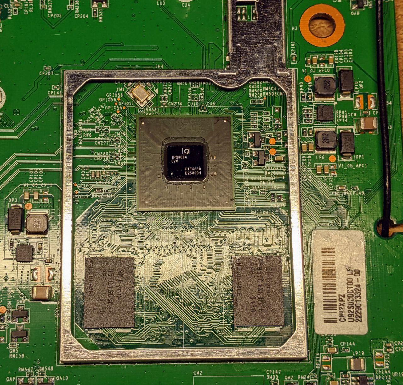
I had a broken old tablet with two SKHynix H5TQ4G63MFR-PBC chips, which is a exactly same package as in router. I've swapping it and router boots well, but didn't recognize all RAM size.

After I've flashed in mtd4 (DDRCONFIG) dump from EA8500, it recognized 512M, so settings definitely here.
According to this leaked datasheet from similar platform, I've found on offset 0x83 in mtd4 value 0x0D for 7500 and 0x0E for 8500. Which corresponds with number of rows for DDR devices.
As my new RAM has a 15 bit row address, I set 0x0F in this byte and voila

Actually it is not that simple, as it is requires custom openwrt build with corrected memory size in dts. But it is possible to flash 8500 official image and it works fine (except switch ports names) with 512M.

Flashing mtd4 from U-boot:

nand device nand0
ipq_nand sbl
tftp $loadaddr mtd4_ea8500.bin
nand erase 0x540000 0x120000
nand write $loadaddr 0x540000 0x120000

You can find mtd4 images in my repo https://github.com/iglooom/rpi-tsop48-nand/tree/master/qca-sbl-dumps/clean for ea7500, ea8500 and modified 1Gb version as well.

For booting ea8500 openwrt image I was needed to change partbootargs and partbootargs2 to values from ea8500.

setenv partbootargs console=ttyHSL1,115200n8 init=/sbin/init rootfstype=squashfs root=31:14
setenv partbootargs2 console=ttyHSL1,115200n8 init=/sbin/init rootfstype=squashfs root=31:16
saveenv

Don't quite sure why it is different from 7500.

@ReDaLeRt maybe this can fit in wiki hardware mods section :slight_smile:

Ah, yes... I just noticed that the firmware I tried earlier for WRT was the DD-WRT, not the OpenWRT. My mistake. There are empty pin headers clustered together. Two 14 pin headers, and one 6 pin header. I looked around for a pinout for this board but so far no luck. I will have to try to probe it and see where things go.

Google found this https://forum.dd-wrt.com/phpBB2/viewtopic.php?t=276769

Ha! yes, that's the one... Guess I'm too technical in my search wording. I have all the rails and cables for setting this up, so I will try and see how it goes.

I connected a USB to TTL adapter to the connection pins and started a terminal program and I get nothing. All the drivers are installed for it. I have RX to TX and TX to RX and Ground to Ground. VCC not connected because the router board is supplying the power. If I type at the console the green light flickers to indicate that data was sent. But all I have is a blank terminal window with a flashing cursor.

it maybe a V1.8 TTL device
check the voltage form TX to GND

3V reading

look's like V3.3 logic
as long as your adapter will work at V3.3
most do some you have to select

Short rx and tx on the adapter and see if you get a reply of your inputs.