Linksys EA8500 uboot damaged after wrongly flashing with empty $loadaddr

Suppose uboot is not signed, then I need to know how much other partitions have been damaged in order to restore the router, methodwise and datawise. At the moment I don't know what kind of tools I need in order to inspect the actual data loss on the NAND chip. I remember maybe 10mb or 20mb have been written with the empty $loadaddr env. If 20mb was the case, then maybe the original data on the chip is completely gone.

Hmm, I just realized, if your u-boot really overwrote something at address 0x0, then it completely destroyed SBL1, which is a important for boot sequence and as I found is perhaps unique for particular router.

Interesting update, I was wrong bout unique SBL1 per router.
Recently I've got dump from another user and it is almost identical with those dumped by @abij earlier.
Seems to be SBL1/2/3 shared with multiple routers in same production batch / hw revision.

So, theoretically there is router which can help me ))
My ea7500v1 is imported from US and has s/n 18L10C6C518659, MAC C0562735607E.
If anyone has another one with closest values, feel free to write me :slight_smile:

PS: I've spot presumably the main difference, in devinfo partiotion my has modelNumber=EA7500, but two others modelNumber=EA7500-HK and modelNumber=EA7500-UK.
Perhaps US model has a different set of bootloaders.

HI, you want to find someone has EA7500v1 and halp you, but this Topic shows EA8500 in title.

Seems to be I steal this topic from @abij :slight_smile:
But he needs dump for his router as well.

I don't think 7500 owners with working routers would open this topic anyway.
I've found on this forum some other members with 7500 and PM it in case they can help.

Hi, couple days ago I finally can recover my EA7500v1.
Thanks for guy who developed https://pypi.org/project/qcom-nandc-pagify/ and described how SBL partitions works.

What I have done.

Need direct connection to NAND flash. On EA7500v1/EA8500 it is possible by using testpoints on PCB, which is even labeled by manufacturer.
I've superglued pinheaders onto PCB, and after that soldering wires between them and testpoints.
On this picture I've labeled which is which.

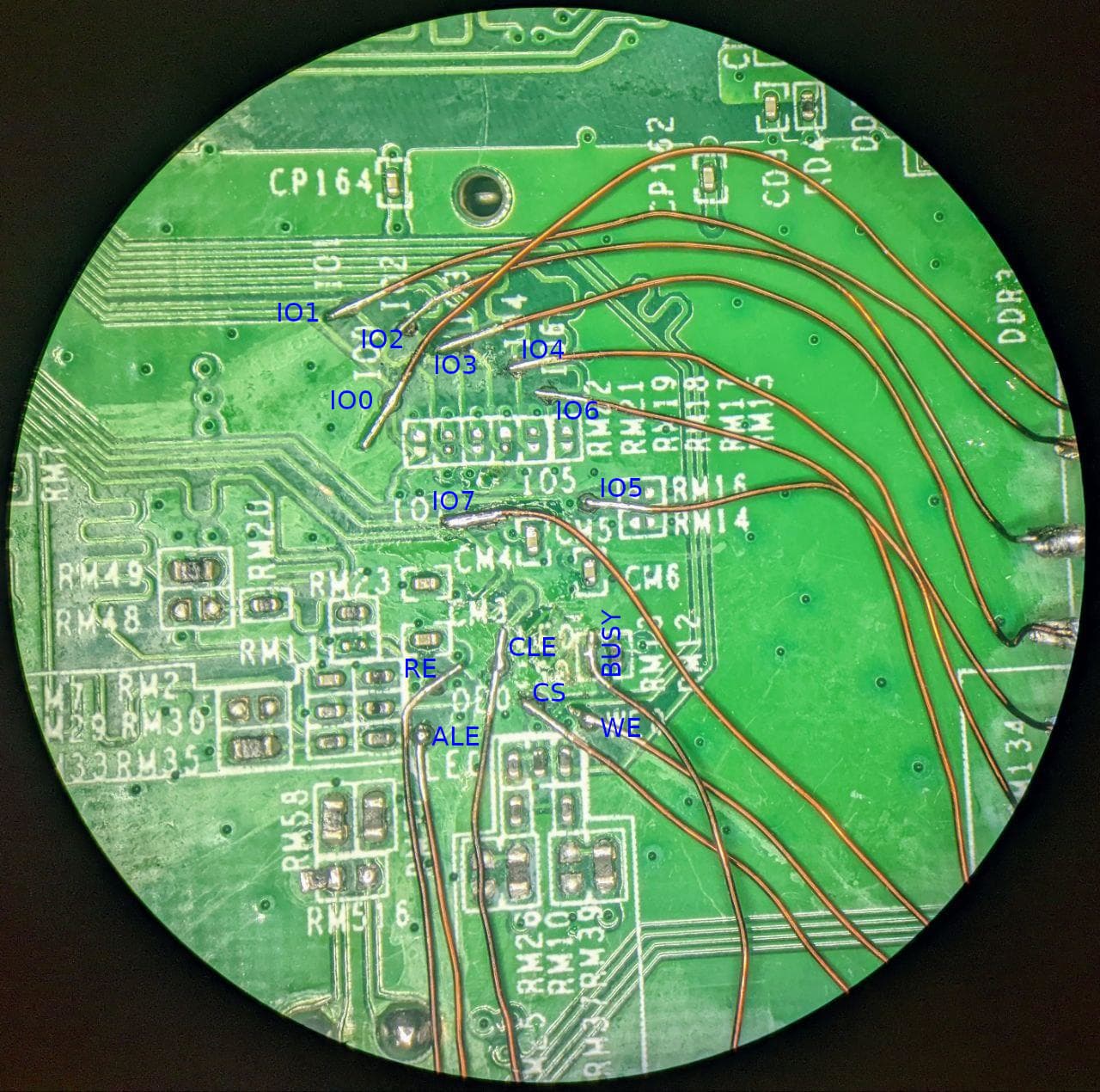
If you have programmer capable to flash 8bit parallel NAND flash, it is easy.
I've try to do it on cheap and used for this purpose raspberry pi b+ which just laying around.
I found project which is implemented bitbang nand flasher. I forked and adapted for my particular Spansion S34MS01G2 nand flash.

Connections described in source file. GPIO layout can be found there https://pinout.xyz/

BUSY GPIO3
ALE  GPIO4
CLE  GPIO5
RE   GPIO6
CS   GND
WE   GPIO7
IO0:IO7  GPIO8:GPIO15

And of course ground from RPI needs to be connected to router's GND. In my case it can be accessed on UART pinheaders.
About power supply, NAND should be supplied by 1.8V, but RPI is a 3.3V.
From electrical point of view it is wrong, but in my case I didn't connect any power to router at all, I discovered that NAND seems to be powered through pull-up resistors from RPI, and 1.8 rail on router was about 1.9v, seems reasonable.
Reading and writing operation was remarkably well, and I decided to leave it without additional supply.

After wiring you can check connection by running

./rpi-raw-nand-v3 150 read_id

Program reads ID from flash and should recognize it as S34MS01G2
If all works fine you should dump existing content of flash, just in case.

./rpi-raw-nand-v3 150 read_full 0 7936 backup.bin

This dumps from mtd0 up to mtd12

You should always use read_full instead read_data, at least for qualcomm propietary partitions, as OOB contains actual data.

Recovering process is a bit messy, as you need dumps from someone who can dump mtd0-mtd12 from working router, but qualcomm nand driver in 5.4 kernel has a bug. Driver removes ECC from dump, but not all, leaves some chunks of it. I've wrote script for recovering actual data and stripping all unnecessary parts.
On the other hand nand driver in 5.10 kernel can correctly dump from mtd0 to mtd8, but corrupts mtd9 (u-boot). So in my case preferred method was get full dumps from 5.4 kernel router.
On working router you need to install nand-utils package and run commands

nanddump -f /tmp/dumpmtd0.bin -o -n /dev/mtd0
nanddump -f /tmp/dumpmtd1.bin -o -n /dev/mtd1
nanddump -f /tmp/dumpmtd2.bin -o -n /dev/mtd2
nanddump -f /tmp/dumpmtd3.bin -o -n /dev/mtd3
... and so on

Then feed this dumps into strip_ecc.py script and you've got clean data.

After that we need to prepare raw data for flasher by adding ECC and other Qualcomm specific things.

qcom-nandc-pagify --infile mtd0_strip.bin --outfile mtd0_ecc.bin --ecc rs_sbl
qcom-nandc-pagify --infile mtd1_strip.bin --outfile mtd1_ecc.bin --ecc rs_sbl
qcom-nandc-pagify --infile mtd2_strip.bin --outfile mtd2_ecc.bin --ecc rs_sbl
... and so on

Flashing new data.
You should always try to save your mtd8 (ART) partition as it contains unique calibration data for this particular device.
As wel as mtd12 which contains serial number and other no so important stuff.

Before you can write into NAND it needs to be erased. Erasing performed by big blocks, in this case by 64 pages. Each page is a 2048 byte.
For example if you need restore SBL1, you need to erase pages from 0 to 127. Is is first two blocks.

./rpi-raw-nand-v3 150 erase_blocks 0 2

Then you can write new data onto it

./rpi-raw-nand-v3 150 write_full 0 128 mtd0_ecc.bin

Partitions table from EA7500v1

No	Name		Start		Start page	Start block		Size		Size pages	Size blocks	ECC
0	SBL1		0			0			0				0x40000		128			2	 		RS_SBL
1	MIBIB		0x40000		128			2				0x140000	640			10	 		RS_SBL
2	SBL2		0x180000	768			12				0x140000	640			10	 		RS_SBL
3	SBL3		0x2c0000	1408		22				0x280000	1280		20	 		RS_SBL
4	DDRCONFIG	0x540000	2688		42				0x120000	576			9	 		RS_SBL
5	SSD			0x660000	3264		51				0x120000	576			9	 		RS_SBL
6	TZ			0x780000	3840		60				0x280000	1280		20	 		RS_SBL
7	RPM			0xa00000	5120		80				0x280000	1280		20	 		RS_SBL
8	ART			0xc80000	6400		100				0x140000	640			10	 		RS
9	APPSBL		0xdc0000	7040		110				0x100000	512			8	 		RS_SBL
10	u_env		0xec0000	7552		118				0x40000		128			2	 		RS
11	s_env		0xf00000	7680		120				0x40000		128			2	 		RS
12	devinfo		0xf40000	7808		122				0x40000		128			2	 		RS

In this table I place page and blocks numbers, for writing and erasing.
Don't substitute page numbers in erase_blocks command!
In ECC column shown which format was used in partition. Description and differences between them, you can find in qcom-nandc-pagify docs.

For successfully boot in U-Boot you need all chain from SBL1 up to RPM plus APPSBL.

Recovering process can be observed by hooking logic analyzer/oscilloscope up to one of the nand's data pin.

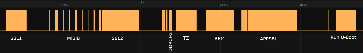
This is a chart I've captured on my router and marked what partitions loading. If boot process fails after some stage, you can figure which is caused.

In my repo https://github.com/iglooom/rpi-tsop48-nand/tree/master/qca-sbl-dumps/raw-nand-dumps you can find raw NAND dumps which I've dumped from working router after recovery. You can simply flash it by external flasher.
I can't check is this dumps can work on 8500, but as I upgraded RAM on my 7500 I've flash mtd4 exactly from 8500 dump and it recognized 512M. So, it seems to be should work on real 8500 too.

And after all of that I've performed some tests, and it seems to be impossible to correctly flash this partitions from OpenWRT, it always corrupted by driver in some way.
Read-only flag on those not a coincidence, don't try this at home :slight_smile:

3 Likes

Initially I thought it can be posted on wiki, but not sure now, as it is not a complete guide to unbricking, and it rather difficult too.

@abij if you eventually can repeat this, maybe you can write instruction more user-friendly, and more english-speaking :slight_smile:

And yep, I was wrong about SBL signing, it is not a secureboot. It just kinda bug in kernel which can't write and read correctly and produces difference between routers.

1 Like

I can help posting that to the wiki, as a regular maintainer for the EA7500 + EA9500 + EA8300 wikis. :smiley:

Do you agree with?

1 Like

Yes, sure, thank you!

1 Like

And I finally figure out how we can obtain correct dumps from working router on ipq806x without soldering or doing some hacks.
I've discovered for myself command 'ipq_nand' in u-boot, this command can switch between SBL and usual ECC formats, so we can dump SBL partitions from u-boot.

Here is how I done this

nand device nand0
ipq_nand sbl
nand read $loadaddr 0 0xc80000
tftpput $loadaddr 0xc80000 192.168.1.254:dumpmtd0-7.bin

nand read $loadaddr 0xdc0000 0x100000
tftpput $loadaddr 0x100000 192.168.1.254:dumpmtd9.bin

ipq_nand linux
nand read $loadaddr 0xc80000 0x140000
tftpput $loadaddr 0x140000 192.168.1.254:dumpmtd8.bin

nand read $loadaddr 0xf40000 0x40000
tftpput $loadaddr 0x40000 192.168.1.254:dumpmtd11.bin

This is clean dumps only with data, with correctly stripped ECC, it can be passed to qcom-nandc-pagify and you have get dumps suitable for external flashers.

2 Likes

Will you able to ask RadioOperator to dump his 8500 mtd0 - 12 partitions using what you have just found? Maybe I can try them on my 8500?

We can ask @RadioOperator here :slight_smile:
Doing this through U-Boot is a bit more complicated then usual and requires shutdown router.

But I almost sure that dumps which I already composed can work on 8500 too. So you can try it first. Don't forget to dump existing data in first place.

Hi, I I did a google search for my problem with an EA2700, and this is the only page that came up that looks remotely useful. Would you be able to point me in the right direction? I have a router that I need to replace the NAND flash on. I acquired new nand flash but I have not been able to find an image to flash to the new nand. I have a burner for it using some difficult to understand software (written in Polish). I managed to figure out how some of it works using google translate. I tried flashing it with a wrt trx file and it does not solve the problem. The router no longer has a green light to indicate booting, it is just blank. Is there somewhere that I can get a complete Nand image that I can use? From your description it seems as though there is supposed to be a boot loader that I am missing. The software I am using for flashing is "Nand Lite!", the flash nand is a Hynix H27U518S2CTR. I'm using Windows 10.

Note: I also tried copying the old NAND to the new one. Same result. At least with the old chip I was getting a green light briefly, but with the new I get nothing. I bought 5 of them, and tried a second one with the same result - no green light.

What the model of original NAND chip and what's wrong with it? Why you decided to replace it?

According wiki it seems to be used CFE bootloader, maybe you can repair router via tftp https://openwrt.org/docs/techref/bootloader/cfe

You can't just burn *wrt image into flash. It always should contain at least bootloader, and often some more stuff. And especially for NAND it should contain correct ECC information in OOB region of nand's pages.

The router would not boot. It would show a green light, then light would go off, then green light would flash. Tech support page said that blinking green means firmware error. I tried the reset button, same results. The setup menu was not accessible through the 192.168.1.1 address. I tried flashing it with the recommended software by hooking up my laptop through one of the ethernet ports and using the reset button, holding the button down on start, running the software to flash with the latest firmware update (Firmware was downloaded from the manufacturer site), then releasing the button. The software connected and said that it flashed successfully, but still the same result, router would not boot and had blinking green. Setup menu not accessible. I tried the same with the WRT firmware for this model. Same result. So I figured that the chip was bad. The tech support said that blinking green was a firmware error, and blinking red was a hardware failure. The device is one that was left behind at a motel by a guest. The power supply had failed.

The NAND chip is the exact replacement model.

I made an image copy of the original NAND to a file with the burner software and copied it to the new NAND hoping that if it was just a bad segment somewhere, the boot loader might still let me flash the new firmware image to the new chip. But unfortunately I don't know how the software for the burner is making the copy because it isn't in English and is hard to understand. It also does not give any intuitive information or help as to what each of the software functions do. With the new chip in place and with the copy on it, I don't get any light at all :frowning: . I might have to try putting the original chip back on. I wish these things were socketed, it would make life so much easier. - Update: Looks like the reader is only saving 67MB from the NAND flash to my hard drive. I will have to try and find out how to image copy the whole chip.

Since your chip is a 512 MBits / 8 = 64 Mbytes it looks okay that reader saves 67MB file. Seems it contains OOB data too.

Does router outputs anything on UART?

I talked to the software author. I sent him a copy of the backup I made and he said it looked good as well and that it should copy over just fine. The software author says it looks like it uses 1 bit parity. I went through the steps of copying it to the new chip, verified its contents, soldered it back on the board, and nothing. I checked VCC for power and the chip is powered.
The router does not have a serial port.
Maybe there is data corruption on the original chip? I'm not sure what else to try.