I was reading the documentation for accessing the serial connection on the EA7500 and I am a little confused about the methods shown for the 3.3V logic vs the 1.8V logic.
On the photo for the 1.8V logic method, there seems to be a couple of components removed near the RX, TX and GND leads. They appear to be small black squares with the text "PK55C". The documentation doesn't really make mention of them or how to remove them, or if they need to be replaced afterward.
Another question I have is about the 3.3V logic method. There are normally some pins that you could connect jumpers to, which have been removed in the photo in favor of a soldered connection so that resistors could be connected as well.
I am also wondering how the pins were removed and if it was really necessary? Couldn't the resistors be spliced into the jumpers and then placed on the pin, or would that change the resistance level?
Thinking about getting one of these cables to interface depending on answers.
Yeah I am just unsure about how to actually make the connections. I wanted to opt for the 1.8V method because I am not even sure where to get resistors now that Radioshack is gone--it's been a while since I've done any small electronics work. But I'm concerned about what those black pieces were that seem to be missing, and would like to avoid having to solder onto the board if possible.
I'm thinking that if I used the first cable I linked to that I could recreate the 3.3V logic like so:
Red wire (5V) to Pin 1
Green wire (Tx) to Pin 2
White wire (Rx) to Pin 3
Black wire (Gnd) to Pin 5
Then splice in 3k Ohm Resistors to the wires:
1 Resistor spliced to connect Red (5V) and White(Rx) wires
1 Resistor spliced to connect Red (5V) and Green(Tx) wires
I believe that would be equivalent to the 3.3V logic image:
But I'm not sure if it changes anything splicing the resistors onto the wire leads versus soldering straight onto the board?
Those are transistors which shift the logic level from 1.8 to 3.3 volts. Since the intended use of the router doesn't include the serial port, the manufacturer may leave them off the board to save cost.
If your board doesn't have transistors then you need to follow the first picture and solder onto the transistor pads-- which lead directly to the CPU-- and use a 1.8 volt interface.
If your board does have the transistors then you can connect a 3.3 volt interface to the pin pads. Additional resistors should not be needed.
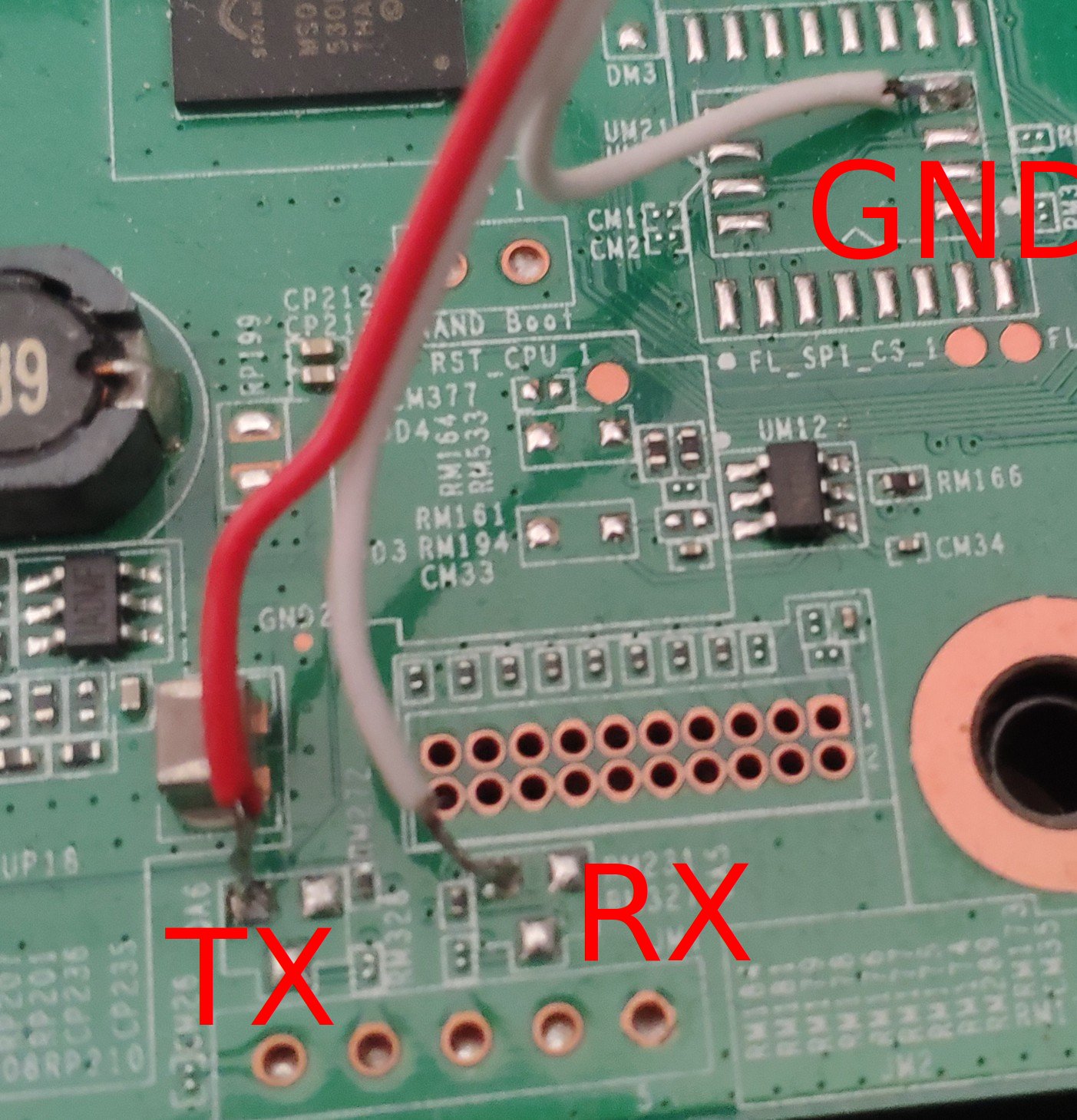
Bummer, looks like I didn't have the good luck to have one with pins and transistors in place. So looks like I'll need to solder onto the board with the 1.8 method.
One other difference I noticed is that where GND is located on my board is a flat copper spot instead of a raised lead/tin/whatever bump. Is that going to be easy to solder on to?
The other pictures also didn't really give a lot of perspective to just how small these connections are. I've never been too good at soldering and I'm pretty sure I would inadvertently drop some on the nearby connections. Is there anything I can put on them to keep the solder from sticking in case I'm too sloppy? I was thinking some Arctic Silver "Ceramique" thermal paste I have might work because it's supposed to be not be electro-conductive.
Otherwise I figure I'll just need to get creative to find something shield the nearby connections.
Does anyone here have any idea how to do it without soldering or a basic guide? I read the wiki but how do I connect USB devices/electronic leads without soldering/unsoldering? to be clear i saw the 1.8v piece in the wiki
Personally, I probably wouldn't bother with adding the resistors and voltage level shifters and use an 1.8V capable FTDI FT232RL adapter instead. Just keeping the leads pressed down firmly to the pads 'might' succeed, but especially for anything more involved, soldering the connection would be safer/ more reliable.