LAN-bridge configuration like AVM in OpenWrt

Sorry to taking your time. maybe I have a massive thinking error because of my wiring. I would like to show it, maybe someone can check. Maybe because of that already it can't work.

  1. Router OpenWrt port 1 to switch
  2. One cable from switch to lower floor to port 1 from OpenWrt AP 1
  3. Port 2 OpenWrt AP 1 to switch
  4. From switch one cable to second floor port 1 OpenWrt AP 2
  5. Port 2 OpenWrt AP2 to switch.....

Can this work with VLAN between the OpenWrts and the end devices are then connected to the switches? Otherwise how should I wire it correctly?

Is your switch managed or unmanaged?

If it's a managed switch, you can use VLAN trunks. That's one physical cable carrying several logical VLANs. IMHO the easiest configuration is to configure all VLANs as tagged on this port. The advantage is that you only need a single cable to carry all VLANs. On your switch you can then configure the remaining ports as "untagged" as you require for your Ethernet devices.

If it's an unmanaged switch, matters are a bit more complex. You can still use tagged VLANs, but the switch won't be aware of this and will not be able to isolate the ports. Hence, you have a risk of mixing up guest network and private network if you add additional wired devices to the switch. If only the APs and routers are involved, an unmanaged switch should work fine.

In both cases you will only need one cable per device.

As an alternative, you can use two cables with untagged VLANs, but then you cannot mix them at an unmanaged switch since you have to isolate the different networks. Thus, you need either a managed switch to perform the isolation (but then you can use VLANs anyway) or two switches (but given the cost and power consumption of a switch, that's not a very economical solution).

An example (my setup):

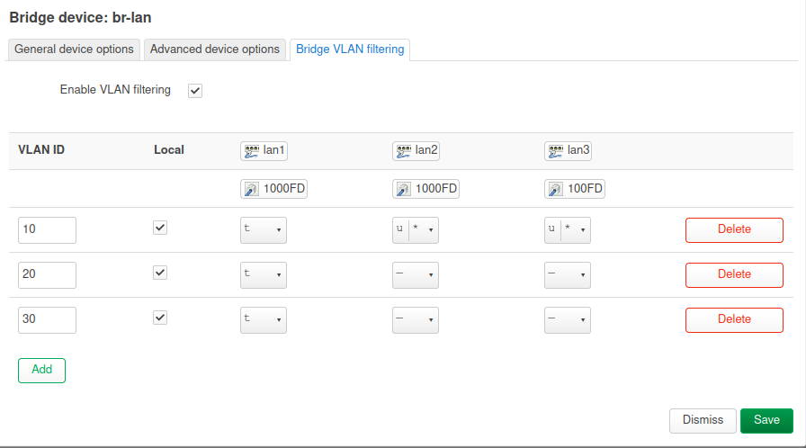
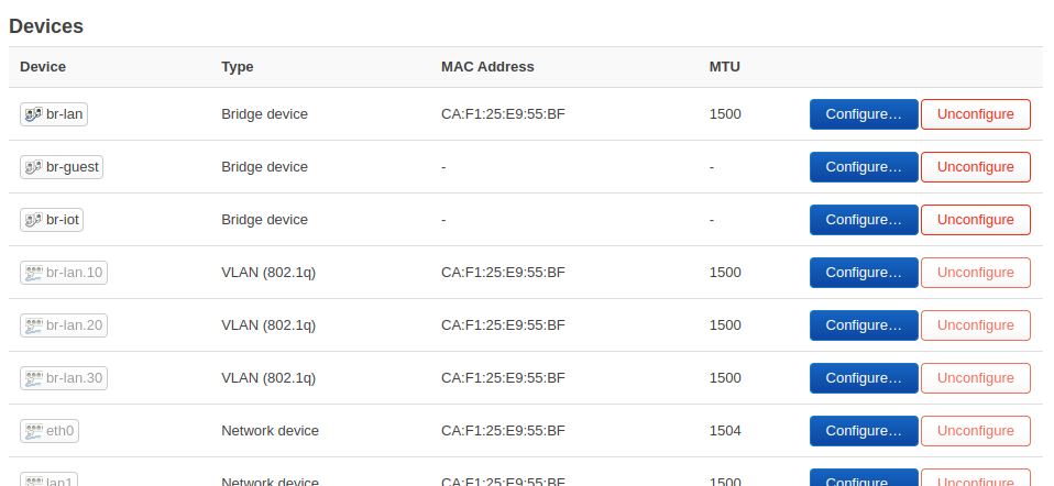
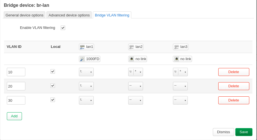
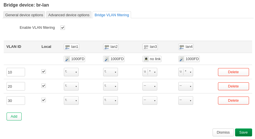
The router - Ubiquiti ER-X, only lan1 is used as VLAN trunk port, so this port is configured as "tagged" on all VLANs. Please be aware that this is a DSA device. 4 defined VLANs:

  • 1: Management interface
  • 100: Modem, only the router and the modem are in this VLAN; I have a PPPoE connection over VLAN 100
  • 200: Private VLAN for the majority of devices
  • 300: IoT VLAN for all "insecure" devices

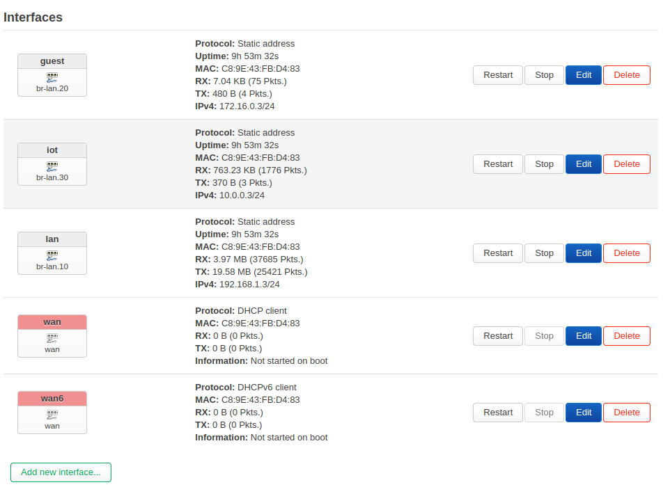
The main router provides three different DHCP servers in different subnets.

/etc/config/network:

config device
	option name 'br-lan'
	option type 'bridge'
	list ports 'eth0'
	list ports 'eth1'
	list ports 'eth2'
	list ports 'eth3'
	list ports 'eth4'

config interface 'lan'
	option proto 'static'
	option netmask '255.255.255.0'
	option ip6assign '60'
	option device 'br-lan.300'
	option ipaddr '192.168.17.1'

config bridge-vlan
	option device 'br-lan'
	option vlan '1'
	list ports 'eth0:t'
	list ports 'eth1'
	list ports 'eth2'
	list ports 'eth3'
	list ports 'eth4'

config bridge-vlan
	option device 'br-lan'
	option vlan '100'
	list ports 'eth0:t'

config bridge-vlan
	option device 'br-lan'
	option vlan '200'
	list ports 'eth0:t'

config bridge-vlan
	option device 'br-lan'
	option vlan '300'
	list ports 'eth0:t'

config interface 'Management'
	option proto 'static'
	option device 'br-lan.1'
	option netmask '255.255.255.0'
	option ipaddr '192.168.20.1'

config interface 'Haustechnik'
	option proto 'static'
	option device 'br-lan.200'
	option ipaddr '192.168.18.1'
	option netmask '255.255.255.0'

config interface 'modem'
	option proto 'static'
	option device 'br-lan.100'
	option ipaddr '10.0.0.1'
	option netmask '255.255.255.0'

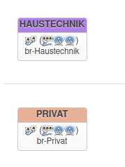
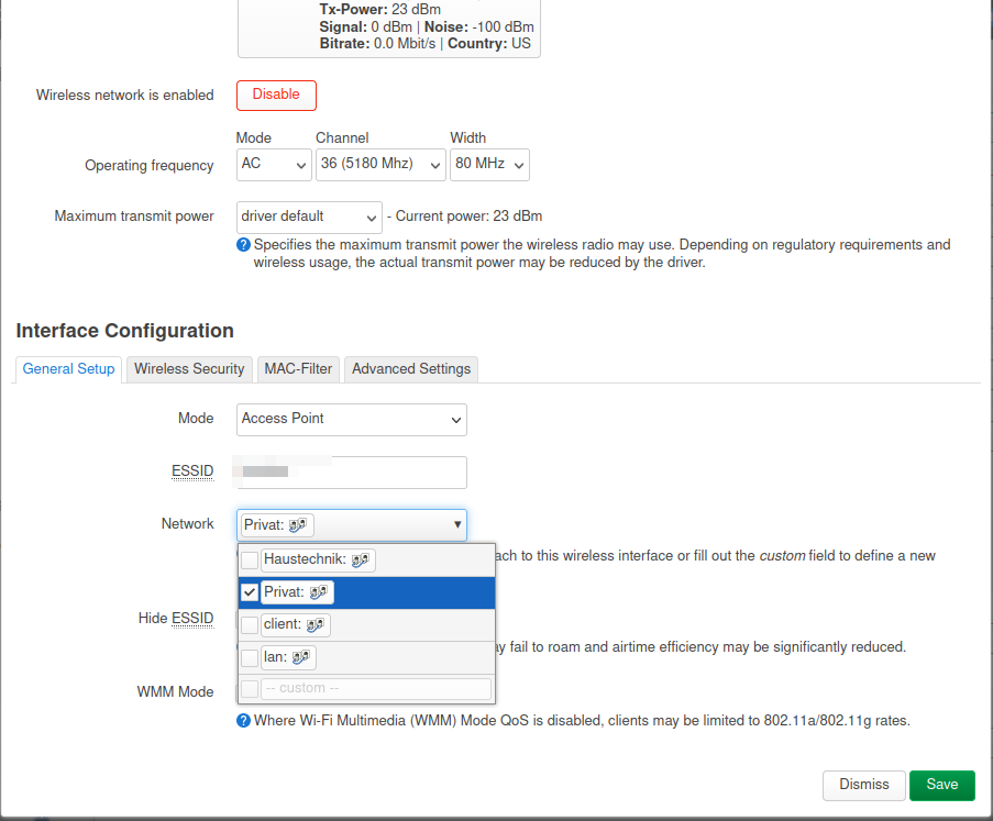
And the configuration of one AP (only has one Ethernet port anyway; the bridges are required for attaching the WiFi interfaces). Each AP has a static IP on VLAN1 and DHCP clients on VLAN1, VLAN200 and VLAN300 (so they all receive multiple IPs from different subnets). One WiFi interface is then attached to br-Private and the othter to br-Haustechnik.

config device
	option name 'br-lan'
	option type 'bridge'
	list ports 'eth0.1'

config interface 'lan'
	option device 'br-lan'
	option proto 'static'
	option ipaddr '192.168.20.60'
	option netmask '255.255.255.0'
	option ip6assign '60'

config interface 'Client'
	option proto 'dhcp'
	option device 'br-lan'
	option hostname 'eap225-Mgmt'

config interface 'Private'
	option proto 'dhcp'
	option hostname 'eap225Private'
	option device 'br-Private'

config interface 'Haustechnik'
	option proto 'dhcp'
	option hostname 'eap225Technik'
	option device 'br-Haustechnik'

config device 
	option name 'br-Haustechnik'
	option type 'bridge'
	list ports 'eth0.200'
	option macaddr 'xx:xx:xx:xx:xx:xx'
	
config device 
	option name 'br-Private'
	option type 'bridge'
	list ports 'eth0.300'
	option macaddr 'xx:xx:xx:xx:xx:xx'

On the router, the remaining Ethernet ports can be used by regular devices and are configured as "Management". The AP cannot be used by non-VLAN-aware devices as it's tagged only.

1 Like

Thank you for your time and the detailed informations :slight_smile: It was all very complicated for me at the moment and I think I don't understand all at the moment. I'm think I have to read a lot more :slight_smile: to understand.

My switches are not managed. I have 3 Netgear GS116 but if it is much easier then I like to exchange them in managed switch maybe something like Netgear GS305E?

If I understood correctly the following is not possible.

Router port 1 (VLAN tagged LAN/GUES/IOT) to switch and from there to AP1 to port 1 is not possible? Because the switch is not managed right?
So I have to look somehow that port 1 of router and AP are directly connected. This way I can provide the WLANs on the respective floor. The switches would have to be connected to port 2 of router or AP because port 2 is untagged and the clients fall into the normal LAN, which is ok in my case.

Alternatively I buy managed switches because it is much easier and you have all options.

Should it better I buy managed switched? :slight_smile:

You should be able to get it working with your unmanaged switch, but you will need a different configuration than mine (I never tried that as I have completely switched to managed switches):

Configure the one VLAN, that you require on the Ethernet ports, as "untagged" and set its PVID in the VLAN configuration. The other VLAN, that is only required to communicate with the APs, is "tagged" on both ends. Now all Ethernet packets from your wired ports do not have a VLAN tag and are interpreted correctly by the router. However, the Guest WiFi is bridged to a tagged VLAN and all packets from this VLAN do have the tag. The router can therefore distinguish the separate networks. This still requires just one cable for each AP.

I would try this approach first and not replace the switches. If you trust your wired clients and don't need other managed stuff, there is IMHO no real reason to exchange them.

Do not go for the really cheap managed switches. I had the TP-Link equivalent (GS108E) which is real crap. If you want to go down this route, invest in the next better device - on some of them you can even run OpenWrt (e.g. the Netgear GS308T or the Zyxel GS1900 series).

1 Like

Because of your valuable tips I have decided to make it a little easier for myself and I got now a managed switch GS308T.
My new planned setup will be....

  1. Router port 1 (tagged) to port 1 of AP(1).
  2. Router port 2 (untagged with PVID) to unmanaged switch for "normal" LAN.
  3. AP(1) port 2 (tagged) to port 1 of AP(2)
  4. AP(1) port 3 (untagged with PVID) to unmanaged switch for "normal" LAN.
  5. AP(2) port 2 (tagged) to managed switch for management from other VLANs via wire.

So I should have different WLANs as VLAN at each AP and at AP(2) even the VLAN by cable.

This should work and possible way right? Or would it be better to wire to a managed switch immediately at point 1 and then manage all other components from that managed switch?

This should work. Just for the sake of completeness: You don't need (4) if it's the same unmanaged switch as (2). If you're talking about a different one (you mentioned several GS116), then yes, that's right. Same is true for 5.

You can stick with the stock firmware on GS308T or install OpenWrt. If you do the latter, you'll end up with the same configuration interface than on the router which is what I prefer.

The exact network layout depends on your requirements, especially regarding throughput: Cascading multiple switches means that all traffic from a downstream switch needs to pass through a single wire to an upstream switch. In larger environments, this could create a bottleneck - that's why 10G is often used as interconnect.

In my home, I have several switches cascaded because I can't run more cables in certain areas - and I don't want to invest in 10G switches (I have a GS1900-24E, a GS1900-24HPv2, a GS308T, a GS108Tv3 and a GS1900-8HP in different cascaded configurations).

1 Like

Yes they are different switches, cool, then that will be my weekend task to implement this :slight_smile: I will report again :slight_smile: Thanks for your confirmations.

EDIT: Yet another question. Does it make a difference if I connect on point 1 direct to the managed switch and then to the APs? Would it be the same in the end? Because the different VLANs could I manage should be possible on the existing ports of the APs or?

That's what I meant with throughput - both solutions will work, but you might limit throughput for some clients if you have a lot of traffic:

GS116 - AP - GS308T means that all traffic from GS116 has to pass through the single wire from the AP to the GS308T, together with the AP's traffic
GS116 - GS308T - AP means that you separate the traffic and have more bandwidth to the GS308T.

It doesn't make a different for Internet access (unless you have a 1G connection) since that is the bottleneck, but it might make a difference if you have a NAS or other network server (then again the single NAS connection could be the bottleneck).

1 Like

All right I understand, will be the following then not the best solution in my case?

  1. Router port 1 (tagged) to port 1 of AP(1).
  2. Router port 2 (untagged with PVID) to unmanaged switch(1) for "normal" LAN.
  3. AP(1) port 2 (tagged) to managed switch for VLAN configuration possibility from each port there
  4. AP(1) port 3 (untagged with PVID) to unmanaged switch(2) for "normal" LAN.
  5. Managed Switch any Port (tagged) to port 1 of AP(2)
  6. AP(2) port 2 (tagged) for VLAN configuration.
  7. AP(2) port 3/4 (untagged) can use for "normal" LAN

That would be a good concept? Or do you have another improvement?
With this way I mean I have the possibility to provide the VLANs on each floor via WLAN or via cable without bottleneck? Otherwise I have probably not understood everything.

I suggest you just try it. Be sure not to create loops or redundant connections!

Ok I will try, at least on paper I do not see any redundant connections.

Ok I tried but I think I am too stupid :frowning: I thought I almost understood the topic.
I have studied the video again and again and fail already at the very beginning when creating the VLANs on the "router".
I have created the bridge interfaces as in the video series descripes, IOT, GUEST, LAN. As seen in this video at point 13:15.
VLANs in OpenWrt21

I configure on the br-lan device the "VLAN filtering" see on 14:22.
I have my laptop connected to port 2 as recommended to not be excluded when I save the settings.
But as soon as I click on save after I have assigned the inferface to the VLANs, see 18:50, I am excluded.
This is what I configure. My Laptop is on Port 2

The automatic rollback did not work and in the end I had to reset and reconfigure the whole router.
So I don't even get as far as configuring the AP, as you can see on 22:05.... according to the video I should have ended up with my laptop in VLAN99 and could continue to administer.
I am desperate.

EDIT:
What for a status should be the devices on Interface - devices? Should be configure or unconfigure? For my reset there was configure and at all was the same MAC Adress entry as in the br-lan. Now I have click on unconfigure and now lan1, lan2, lan3 and wan have a different MAC as for example br-lan. Before it was the same. How should it be the? Maybe I have a problem there?

EDIT:
Really strange, after a reboot from the OpenWrt (Router) now all devices br-lan, lan1, lan2, lan3, wan have the same MAC, but another like the device really have (note on the label on the device).

The screenshot looks fine. Yes, you will most probably lose access if you don't reconfigure the interface.

AFAIK, the Mac address on your bridges can be same if the devices are in different subnets. You can manually change them, too.

When setting it up the first time, it took me some tries to get straight as well. If you configure you lan2 and lan3 as untagged and hook your computer up there, you will have to reconfigure the LAN interface in the same go so that the device has an IP address. My setup looks like this (eth1 receives an IP address from the LAN interface if a computer is directly attached to it).

Note that I changed the device to br-lan.300 in order not to lose access.

1 Like

Thank you for your answer. I will try again soon. My OpenWrt router was already productive and it was stupid when I play with it and then it doesn't work. No one had wifi in the house anymore :slight_smile:
I now put my old router back up and set up a test environment with my OpenWrt hardware. There I will try a new attempt soon.
In my screen there is not eth1, eth 2 etc.... the ports are called LAN1, LAN2, LAN3...
But I see an eth0 under register "Devices".
This is hardware specific or? Does not matter now? My OpenWrt hardware is a Netgear WAX202 and the APs are WAX206.

I've got it, I'm a big step ahead.......
In principle, I did nothing different than on the weekend, only now in a "test environment" where no "WAN" is available, i.e. no cable is plugged into the WAN port.

My wiring is now as follows:
OpenWrt 1 LAN1 directly with a cable to LAN1 of OpenWrt 2.
OpenWRT 2 LAN2 directly with a cable to LAN1 from OpenWrt 3.

On the other LAN ports e.g. LAN3 or 4 my "normal" LAN (LAN10) is available everywhere. I haven't connected any switches yet, but I will connect them to this LAN3/LAN4. Then the normal LAN should be available at all ports of the switch I think.

Here you can see my settings:

OpenWrt 1:

OpenWrt 2

OpenWrt 3

I think that looks good and everything is configured correctly?
What surprises me is that the interface symbols no longer show any WLAN symbols, only the switch symbols. But WLAN works on every OpenWrt.

Now I just have two questions.

  1. As it looks now I definitely don't need a managed switch for my requirement right?

  2. Then I would like to know what exactly I have to set if, for example, I want to provide VLAN20 on Openwrt 2 on LAN4. Do I then have to set VLAN20 to "Untagged" for LAN4 without PVID?. Is the VLAN20 then available via cable at the port?
    I would like to connect a device with a cable to the VLAN20 at the port.

You mean like this:
image

Did you change the interface assignment on the WiFi page (i just noticed that my country settings are wrong)?

Yes, but I would set a PVID. While the driver should automatically add the PVID if no PVID is defined, some drivers don't do that or don't do it reliably. The managed switch in your router will do the rest, i.e. adding the tag if required and removing the tag if required.

Exactly that... yes I have made the assignment in Wireless. The video tutorial also shows "no" wireless symbols..... but it seems to work.

Because of the VLAN20 I will just test.

With my setup I actually don't need a managed switch right now? Everything is correct and no redundant connections etc.

1 Like

Ok I got it I think. Thank you again very much for your help and patience.
I also think that I have now a lot understood how it works and I now have an original packed Netgear GS308T lying here :slight_smile: But maybe I'll just keep it just in case :slight_smile:
I have now created my final configuration in the test environment. At the weekend I will switch to productive.

I have a total of four VLANs for the following purposes:

  1. LAN (Private - available via cable and WLAN)
  2. GUEST (Guest network - available via WLAN)
  3. IOT (IoT devices - available via WLAN)
  4. Smart (Smart TV with Internet Access - available via cable and WLAN)

Two things are still a bit strange but I think that's nothing bad I hope.

  1. The WLAN symbol is still missing at the "Interfaces" as seen on your picture. But WLAN works.
    Bildschirmfoto vom 2023-02-01 21-28-00

  2. My test smartphone connects to all WLANs except one, no connection is established there, no IP address can be retrieved. I can't find any difference between this WLAN and the others. But my test tablet, however, has no problems and can connect to all 4 WLANs.

EDIT:
Oh no, my main Smartphone have the same problem which I describe in point 2. What could there the Problem? :frowning:

EDIT2:
Fine, I have now already moved everything and it is "productive" now. The smartphones now also connect to the one WLAN without problems, all good now :slight_smile: I hope it remains stable :slight_smile:

I close the topic. I got it to work the way I wanted and everything works. The VLAN configuration can be seen on my screenshot. Thanks for your help and patience andyboeh.

1 Like

This topic was automatically closed 10 days after the last reply. New replies are no longer allowed.