The new ubiquiti Units have to be 'jailbreak" in order to install openWRT.
I sucessfully flashed an openWRT nightly build on a new Rocket M2 XW revision, directly from AirOS 6.2.0 , bypassing the firmware signature.
I also had to compile from trunk and modify the files slightly in order to get a working image.
I may make a bigger post later, explaining what i did exactly. When it works 100%
I know the unit is booting openWRT because of the LED pattern.
but, i can't access the unit, and no wifi is broadcasted.
Maybe in made a mistake in the config files I added to the compilation, i don't know
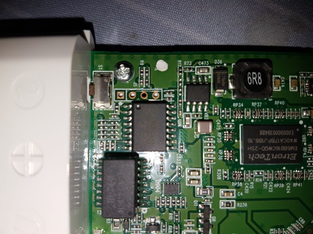
I would like to access the mother board with the JTAG pins, and see what's happen in a serial console.
Problem is, the new motherboards have HOLES and not PINS.
the traces are so tiny that i'm sure i will short everything if i try to solder pins on this
JTAG or serial port? They are two, different things.
If the 1+3 in the silkscreened box, careful soldering of wires would be my approach if only temporary.
If longer term, then I'd use what look to be standard, 0.1" spaced header pins, soldered in place (check the spacing, usually called "pitch" in part specs).
The spring-loaded or "pogo" pins are generally for high-volume, automated-testing use. In these situations, the board is precisely placed on the line in a jig, the connector descends to press against the lands, the test is made, then it lifts up and the next one is put into place, often on automated machinery.
Holes really aren't a problem but those have solder which would need to be cleared out. This could potentially be done with a really small drill bit if you don't want to "solder" at all. Once you have empty holes then take a strip of three regular square pins and plug one end of the pins into the serial adapter, put the other end through the holes and tilt it to the side so it makes contact.
That's easy with the proper tools, my favorite component is a round magnifying glass with the lights.
For the single use there is no need to solder - just put the uninsulated wires through the holes and insert something in the same holes to fix the wires, even the peaces of the stripped insulation. Very quick and unreliable.
Sounds like OP has no experience with soldering so probably best to use one of the temporary connections suggested. For the record in case anyone looks this thread up in the future typically you would de-solder from the bottom of the board to clean the holes out, then solder new header pins in. As noted these are usually 0.1" standard spaced headers, but no guarantees.
If I was doing this I'd put the board in a vice or mount to hold it vertically so that both front and back were accessible. Heat up each "blocked hole" with soldering iron on sufficient heat/power from the back side of the board, and use a solder sucker to vacuum it out from the front. If you don't have one/can't find one the other option is to heat up the solder to melting point and very carefully/quickly blow air from the front side of the board as you remove you soldering tool. Tiny hot beads of solder go flying so be careful but hey, they get out of the hole!
For a beginner... if you have some solid core cat5... chop some strands to about 6 inches, strip 1 cm off each end and pre-tin...
Then one by one... tin them in ... if your gentle... they are strong enough to push through themselves when the existing solder softens...
Route the board side neatly but with a little slack then hotglue ( technically a drop after you do each wire ), to somewhere flat and plastic on the board... ( usually the top of an ethernet port )...
You can now mess with the other ends to your hearts content and not mess around near the pcb... The downside of this method is that the loose ends won't take much of a beating before they need restripping... so be gentle with them and make sure you have slack to redo later...
For rows of stuff / desoldering you really have to have a feel for heat control... And that takes a year or so of practice...
Salut compatriote "Jo Louis"
The holes are currently not filled with solder so that's not a problem, thanks for the technique though
Thanks for the heads up i will test this if the driver inside the "rocket XW" profile doesn't work
Yes I did, it's a rocket M2 XW version, shipped with airOS firmware 6.1.5XW, and unable do downgrade further, so the signature verification is enforced.
a friend of me advised to use the pogo pins, so i will go with that, im out of home for a few days so i will get the parcel later at the post office.
Okay now for the technique I used to install openWRT :
first, we have to spoof the version of the firmware. so airOS accepts it.
i had to patch the openWRT source :
in the build directory
edit this file :
/openwrt/target/linux/ar71xx/image/generix-ubnt.mk
for each “UBNT_version”, change the value to 6.2.0
so it's look like : UBNT VERSION := 6.2.0
Not sure if it's needed, but i created files that pushes a good network configuration by default
this router only has one RJ45 port and it's the WAN (so firewalled), and by default the wifi is desactivated.
so i created config files that redirect ssh and https from wan to lan
again i'm not sure if it's needed, maybe the default config when we build is correct
now we have to bypass the signature verification
the utility that doing the firmware upgrade in airOS is called "fwupdate.real"
we can use a patched version of the utility that desactivates signature verification :
it can be obtained following those instructions (NOT MY WORK, KUDOS TO THEM !):
then you copy the patched fwupdate.real file to the router in the /tmp folder
you also copy the firmware image in /tmp
then you flash by explicitely using the patched upgrade utility :
/tmp/fwupdate.real -m /tmp/name-of-openwrt-image.bin -d
it will flash correctly and the LED patern then match with openWRT behavior. But i'm unable to comunicate with the router. Maybe it's a small problem but i need to access a console to diagnose it.
To roll back to official AirOS firmware, it's easy, just folow standard firmware recovery procedure :
(power on with the reset button pressed for 30 seconds util the LED looks like a christmass tree , then send the file with tftp
on windows, install the tftp utility from the windows optional utilities
then
tftp - i 192.168.1.20 put -official firmare name-.bin
Yes it sounds like you just need to log in by serial and fix the network config. Single port builds are supposed to come up with the port attached to LAN by default. Check that the Ethernet light comes on when you plug in a live cable. If it does not the hardware is probably not being initialized correctly.
How did the pogoplugs work for this? I have a different Ubiquiti board I'm wanting to gain serial access to and am facing the same issue with the header not being there and I can't solder to save myself.