Hello, I wanted to revert my TP-Link WA850RE v2.0 to the latest stock firmware today. I followed the steps from this wiki page in order to do so.
First I downloaded the TL-WA850RE-V2-stripped.bin firmware file to flash using the WebUI. However for some reason it wouldn't let me flash it. (I also tried with the stock firmware and it wouldn't flash for the same reason)
I went and installed libustream-openssl, ca-bundle and ca-certificates so that I could use wget and I downloaded the TL-WA850RE-V2-stripped.bin firmware file to /tmp.
I then proceeded with mtd -r write /tmp/tplink.bin firmware.
My device won't start anymore now. I assume it is bricked. I tried the reset button on the device but this doesn't change much.
Is there a way to fix without opening the device and soldering wires all over it?
If there's no easy fix, how come the wiki instructions lead users to do this?
Any help would be greatly appreciated.
There is no TFTP over LAN on this particular model.
After some more research and actually reaching out to TP-Link support I've concluded that without soldering there's no way to recover this device from a bad firmware flash.
I did try that as instructed in the guide but it wasn't working for some reason.
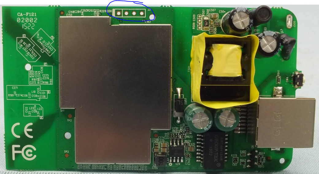
Let's say I was to use the serial port to flash firmware onto this device, how can I locate the RX, TX and GND connectors? I looked for schematics however I was unable to find any.
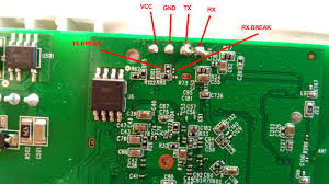
I imagine the next question would be which is which, so here
I found it in form a Web Search, but I can't be 100% sure it's of your device, so I would suggest that youcross check against the instructions here https://openwrt.org/docs/techref/hardware/port.serial under Finding Serial Console
@tmomas
This seems like a photo that was on the old forum. I found the thumbnail on Google but when the link leads to a post about the device on the old forum, without photo though.
If it looks right, coul you add it to the Wiki? I know how to edit but I don't know how to upload an image to include.
The device looks OK. It lacks RX and TX LEDs which can be useful for diagnostics if things don't go as you expect (and it might be overpriced?), but it should work.
As for voltages, my understanding that it should be 3.3 V, even though you don't connect the VCC. I don't know what would happen if you use a 5 V device.
Never connect the positive to the router, you can burn the device, it is safer to plug it in and it will provide the necessary current. The negative, yes, it is necessary to connect it, let's say it absorbs noise during the transmission.
As for the voltages, whether it should be 5V or 3.3V depends on the chip in the device. The safest thing is to use 3.3V, since most of the 5V chips are programmed perfectly with 3.3V. Anyway, nothing happens, since the 3.3V chips usually withstand 5V surges. Do not be afraid, do it, but do not connect the positive, if you do not see anything in the console, change TX and RX.
Things definitely seem informative here, I hope to propely go over the thread by next week.
My time management skills, in conjunction with very busy weeks, have prevented me from being online here.
Hi again, I received my TTL device in the mail today.
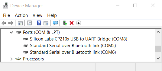
I'm having trouble with the serial connection, unable to read anything in Putty.
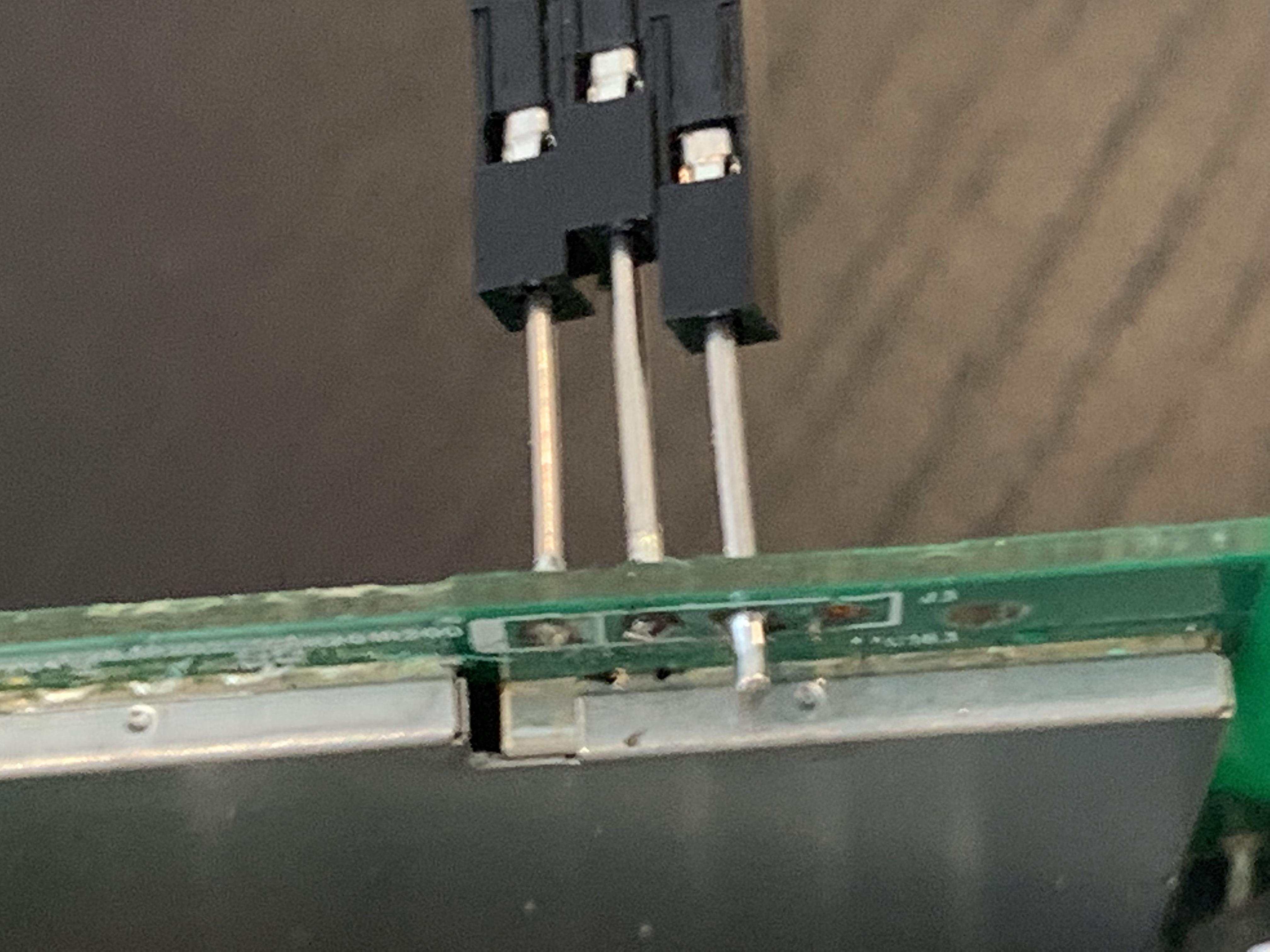
I soldered pins to GND, TX and RX. I know it looks pretty sloppy, this was my first attempt at soldering.
The black cable is GND, green is TX and white is supposed to be RX. I did switch white and green around a couple times just to make sure, but neither gave me any response. http://www.farnell.com/datasheets/1651403.pdf
Am I supposed to fill the VCC hole with solder? Or since I'm using a 3.3V device, should I solder a pin to it and put the white cable on that?
The photos don't show the colours of the cables. But no, you don't need to fill the VCC hole, and you don't need to connect it to anything. In fact some I debricked my device before without even soldering, just using some phone wires and fitting them in the holes.
RX to TX and TX to RX, so if the photo with the marking is correct, white should be in the middle.
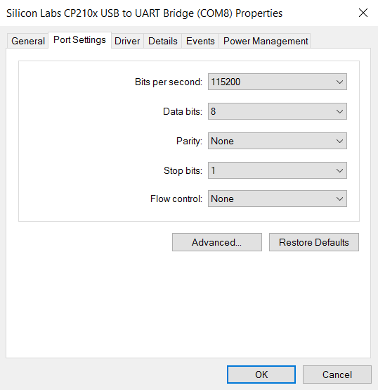
Are you sure you have the driver installed properly on your computer? I imagine you do, or otherwise you wouldn't have a COM port, but it wouldn't harm to double check that first. Secondly, did you try the correct baud rate etc?