Dual‑Boot Modification for CMCC RAX3000M Computing Power Edition (eMMC Version Only)
(eMMC “Computing Power Edition” / 算力版 — eMMC version only)
 WARNING!
All actions described below are performed entirely at your own risk.
This guide is intended for advanced users or professionals with solid soldering skills (including BGA work).
The author is not responsible for any hardware damage caused by improper handling.
Overview
I decided to implement dual‑boot on the CMCC RAX3000M (eMMC version) by adding an SPI‑NAND chip.
Dual‑boot allows selecting which storage device the router boots from at power‑on.
For example:
- eMMC → OpenWrt
- SPI‑NAND → another OpenWrt or Keenetic
Required Tools & Parts
Besides steady hands ![]()
1. Tools
- Soldering iron
- Hot air station
- Proper (non‑active) BGA flux
2. SPI‑NAND chip
I used:
MX35LF1GE4AB-Z4I(≈ $1.4 on AliExpress with coins)
Alternative:
W25N01GVZEIGor similar
3. Resistors (0402 SMD)
- 0Ω (1 pcs)
- 4.7 kΩ (3 pcs)
(You may buy 10 pcs each if available; 100 pcs is unnecessary.)
The 2 kΩ (2 pcs) resistors may be:
- Through‑hole
- Or SMD 1206 — whatever is easier for you to solder
4. Wiring & Switch
- Soft thin wires (recommended AWG28–AWG32 silicone insulated)
- 2P2T slide switch (lever length ≥ 4 mm recommended)


Example:
Soft silicone wires are important — rigid thick wires may tear PCB pads when bent.
Mod Concept
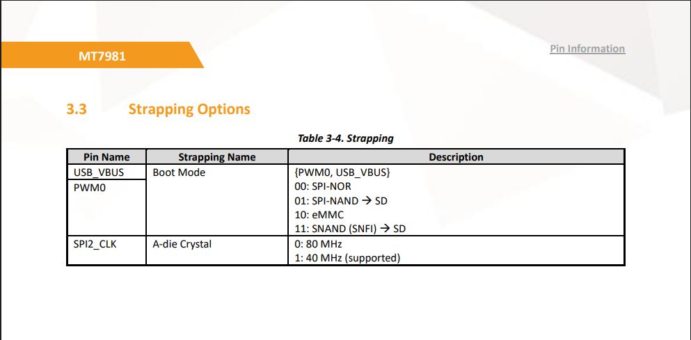
The modification works by changing the boot strapping resistor configuration near the CPU (MT7981B).
The original resistors are 4.7 kΩ.
We do not remove them (impractical).
Instead, we override their logic level:
- Logic High (1)
- Logic Low (0)
Using stronger pull resistors:
- 2 kΩ
This forces the desired boot source.
(See MT7981B datasheet — Boot Strapping section.)
Hardware Installation
 Install SPI‑NAND
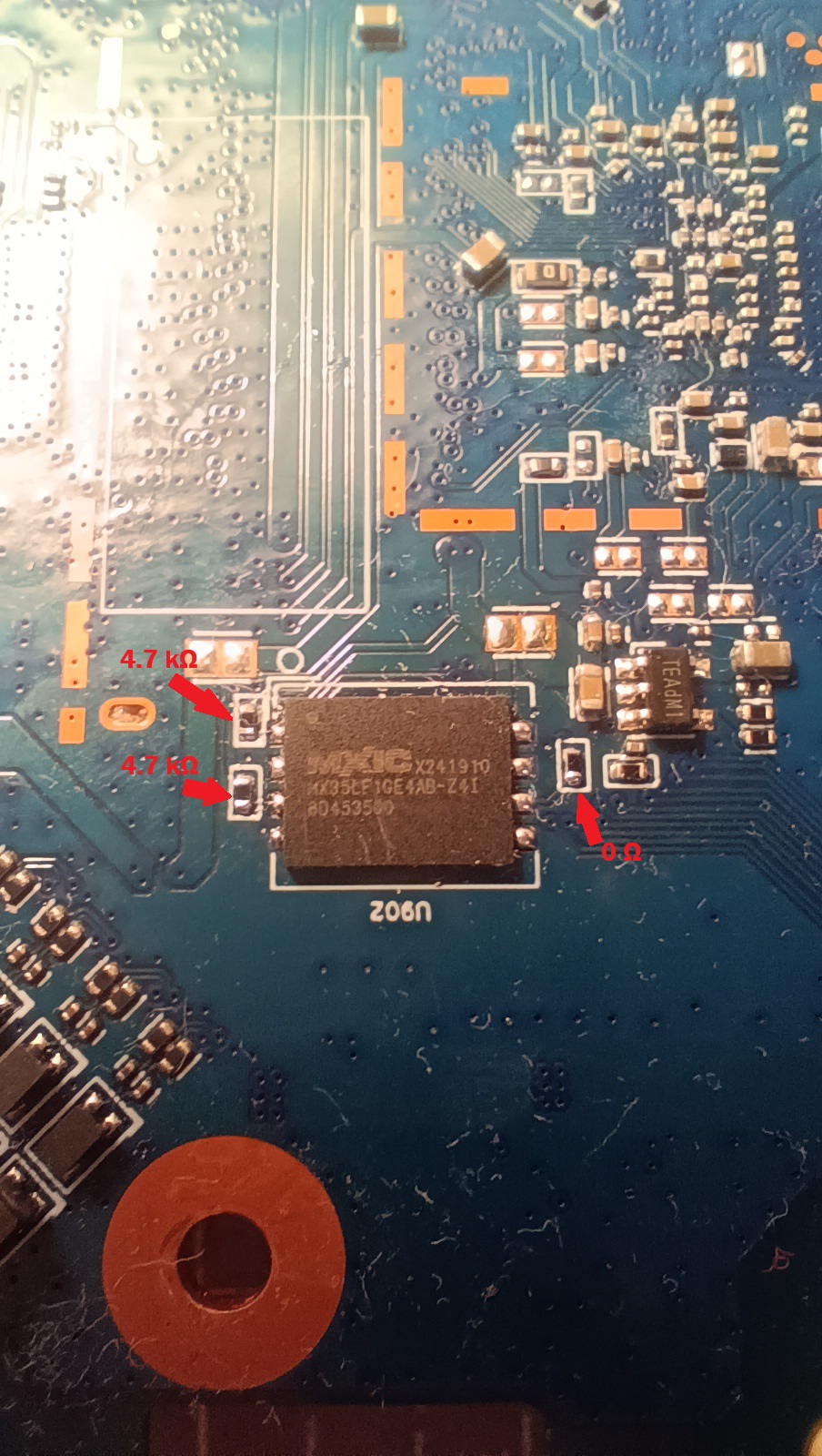
Solder the SPI‑NAND chip on the back side of the PCB (designated footprint).
Add missing resistors:
- 1 × 0Ω
- 2 × 4.7 kΩ
 Add Wiring
Solder 4 thin wires to the specified resistor pads and contacts.
Also add the missing 4.7 kΩ resistor near the button (top side).


![]() Note that the USB port power mod has already been done here - resistor moved for USB_VBUS. Be extremely careful with the USB_VBUS resistor as it's located near the 12V pads - it's highly undesirable to short anything there or leave solder bridges. Why soft and thin wires are needed - if the wires are stiff and thick, they may tear off traces with pads and resistors from the board during bending
Note that the USB port power mod has already been done here - resistor moved for USB_VBUS. Be extremely careful with the USB_VBUS resistor as it's located near the 12V pads - it's highly undesirable to short anything there or leave solder bridges. Why soft and thin wires are needed - if the wires are stiff and thick, they may tear off traces with pads and resistors from the board during bending
 Connect to Slide Switch
Wire everything according to your 2P2T switch layout.

The switch lever (~1.5 mm shaft) almost fits through the ventilation slots near the USB port.
You may need slight filing or widening with a flat screwdriver.
Boot Modes
- Switch position A → SPI‑NAND boot
- Switch position B → eMMC boot
SPI‑NAND Initial Setup
![]() A new SPI‑NAND chip must be erased before use.
A new SPI‑NAND chip must be erased before use.
Use UART boot method:
MTKUartBoot
https://4pda.to/forum/index.php?showtopic=1109762&view=findpost&p=138665859
After booting:
- Connect via serial console
- Press Ctrl+C to enter U‑Boot
- Run:
text
mtd erase spi-nand0
Bad block warnings during erase are normal for new NAND chips.
If needed, repeat the erase procedure once more.
Then start the HTTP server:
text
httpd
Flash Bootloaders
Open in browser:
text
http://192.168.1.1/bl2.html
http://192.168.1.1/uboot.html
Download latest OpenWrt bootloaders here:
Required files:
bl2.bin→ NAND-DDR4-RELOADER.BINuboot→ NAND-DDR4-BL31-UBOOT.FIP
Keenetic Setup (Optional)
For Keenetic:
- Flash:
text
KeenBOOT_RAX3000M_ME.bin
from:
2. Then install full KeeneticOS dump.
Factory Partition Handling
You must extract the factory (mtd) partition from eMMC (via OpenWrt shell + scp or WinSCP).
Then adapt it for SPI‑NAND.
If installing OpenWrt on SPI‑NAND:
Simply replace the corresponding mtdX factory partition.
If installing Keenetic:
More complicated.
In Keenetic format:
- Factory is merged with bootloader.
- Must be combined using WinHEX (or any hex editor).
In KeeneticOS 5.0.x full dump:
- Factory appears twice:
- Offset
0x180000 - Offset
0x300000
- Offset
You must replace both instances.
Assistance
If you need:
- My full dump
- Help injecting your factory partition
Send me a private message — I’ll help if possible.
Source: 4PDA