Aruba AP-105 SPI flash & Rpi

Hello everybody,

I would like to request your help and advise regarding a writting/erasing issue I have on the SPI flash MX25L12835F.

I recently saw that thanks to riptidewave93 work, OpenWRT can be used on Aruba AP-105. Since I had one laying around, I decided to give it a try using the instruction page and the MX25L12835F datasheet.

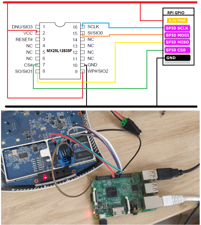
I only had a Raspberry Pi 3 for communicating with SPI and according to some posts over the internet powering the SPI flash on the AP-105 board from your Rpi 3V3 pin would draw a lot of current (because of others ICs connected to the SPI flash) and is likely to destroy the RPI. So I used an old computer power-supply to power the 3V3 VCC input of the SPI flash with this wiring :

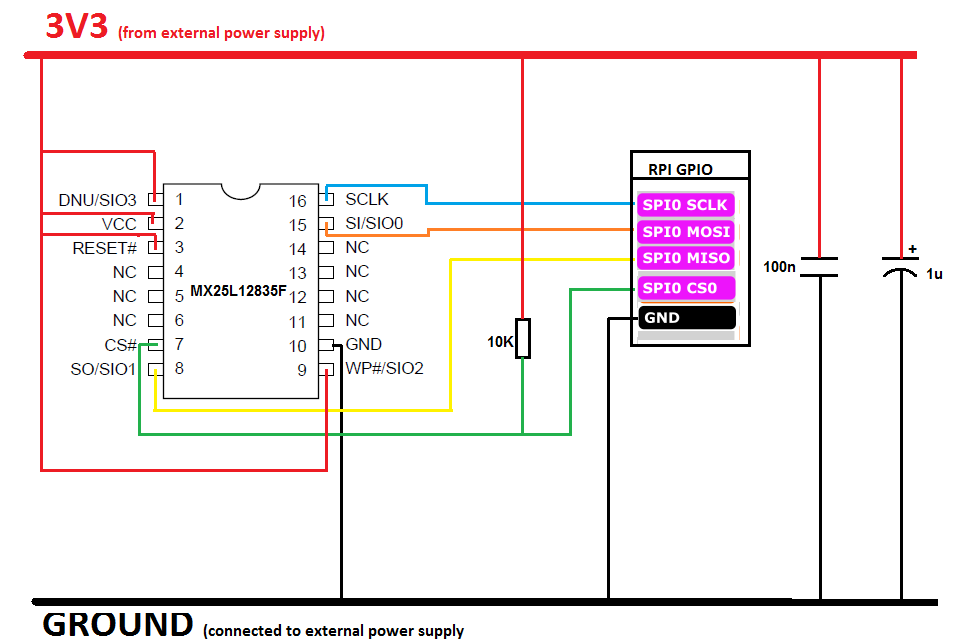
  • Note : the pull-up resistor for the CS line is advised in the MX25L datasheet.

After some fixing :

  • connecting to VCC some floating pins
  • Specifying the SPI clock speed in flashrom (around 15 Mhz). Chip was not detected using default speed.
  • connecting my oscilloscope ground cable to the circuit ground (I still don't know why the power LED of the AP-105 would not turn on without this...)

I was able to read the whole 16 Mb of the SPI flash thanks to the flashrom linux application. I did that two other times and compare the md5sum of the three images to be sure that there were no reading issue.

However, and this is the whole reason of this post (sorry for the long introduction by the way...), I am still not able to write back anything into the SPI flash. flashrom would always give me the same output :

tranxen@nas:/tmp $ flashrom -V -w To_modify.rom -p linux_spi:dev=/dev/spidev0.0,spispeed=16500 -V -c MX25L12835F/MX25L12845E/MX25L12865E
flashrom  on Linux 4.19.97-v7+ (armv7l)
flashrom is free software, get the source code at https://flashrom.org

flashrom was built with libpci 3.5.2, GCC 8.2.0, little endian
Command line (8 args): flashrom -V -w To_modify.rom -p linux_spi:dev=/dev/spidev0.0,spispeed=16500 -V -c MX25L12835F/MX25L12845E/MX25L12865E
Using clock_gettime for delay loops (clk_id: 1, resolution: 1ns).
Initializing linux_spi programmer
Using device /dev/spidev0.0
Using 16500 kHz clock
The following protocols are supported: SPI.
Probing for Macronix MX25L12835F/MX25L12845E/MX25L12865E, 16384 kB: probe_spi_rdid_generic: id1 0xc2, id2 0x2018
Found Macronix flash chip "MX25L12835F/MX25L12845E/MX25L12865E" (16384 kB, SPI) on linux_spi.
Chip status register is 0x00.
Chip status register: Status Register Write Disable (SRWD, SRP, ...) is not set
Chip status register: Bit 6 is not set
Chip status register: Block Protect 3 (BP3) is not set
Chip status register: Block Protect 2 (BP2) is not set
Chip status register: Block Protect 1 (BP1) is not set
Chip status register: Block Protect 0 (BP0) is not set
Chip status register: Write Enable Latch (WEL) is not set
Chip status register: Write In Progress (WIP/BUSY) is not set
This chip may contain one-time programmable memory. flashrom cannot read
and may never be able to write it, hence it may not be able to completely
clone the contents of this chip (see man page for details).
Block protection is disabled.
Reading old flash chip contents... done.
Erasing and writing flash chip... Trying erase function 0... 0x000000-0x000fff:EFAILED at 0x00000000! Expected=0xff, Found=0x10, failed byte count from 0x00000000-0x00000fff: 0xfab
ERASE FAILED!
Reading current flash chip contents... done. Looking for another erase function.
Trying erase function 1... 0x000000-0x007fff:EFAILED at 0x00000000! Expected=0xff, Found=0x10, failed byte count from 0x00000000-0x00007fff: 0x7e01
ERASE FAILED!
Reading current flash chip contents... done. Looking for another erase function.
Trying erase function 2... 0x000000-0x00ffff:EFAILED at 0x00000000! Expected=0xff, Found=0x10, failed byte count from 0x00000000-0x0000ffff: 0xfbb3
ERASE FAILED!
Reading current flash chip contents... done. Looking for another erase function.
Trying erase function 3... 0x000000-0xffffff:EFAILED at 0x00000000! Expected=0xff, Found=0x10, failed byte count from 0x00000000-0x00ffffff: 0x7e95f4
ERASE FAILED!
Reading current flash chip contents... done. Looking for another erase function.
Trying erase function 4... 0x000000-0xffffff:EFAILED at 0x00000000! Expected=0xff, Found=0x10, failed byte count from 0x00000000-0x00ffffff: 0x7e95f4
ERASE FAILED!
Reading current flash chip contents... done. Looking for another erase function.
Trying erase function 5... not defined. No usable erase functions left.
FAILED!
Uh oh. Erase/write failed. Checking if anything has changed.
Reading current flash chip contents... done.
Good, writing to the flash chip apparently didn't do anything.
Please check the connections (especially those to write protection pins) between
the programmer and the flash chip. If you think the error is caused by flashrom
please report this on IRC at chat.freenode.net (channel #flashrom) or
mail flashrom@flashrom.org, thanks!

Please find below the list of things that I tried to fix that without succeeding :

  • Decreasing the SPI speed clock on flashrom down to 100 KHz
  • Forcing the WEL bit to 1 using the SPI command WREN before writting.
  • Trying to only Erase instead of Erase+Write
  • Putting the WP pin to low (which gave the very same output from flashrom...).
  • Forcing reset pin low and back high before attempting a new writing
  • Disconnecting the external power-supply and connecting the AP-105 with its own PSU, waiting for the AR7161 CPU to stop using SPI, connect the SPI wiring from my RPI. That didn't work probably because even if the CPU was not using SPI it was still pulling SC and MOSI to Vcc so my RPI didn't manage to drive these pins at the expected voltage.

I am running out of clues and it is starting to get frustrating... I know there are a few people here (@riptidewave93 and @markbirss) that succeed in writing the u-boot into the SPI flash but I am not sure if the MX25L12835F was still on the main board while they did it.

The only hint I have is about the external power-supply that may lead to writing errors. But if it is the case why the reading did work ? I am not excluding this idea however because this person on another forum that has the exact same problem I had (but not with the very same flash) has resolved it using the board power-supply...

Additional information about my AP-105

I have the early version of the AP-105 which is lacking the reset button that you usually find on the back. Because of that I cannot stall the CPU (AR7161) to prevent it to drive the SPI pins on the SPI flash. I will check on the AR7161 datasheet, maybe there is a reset pin that I can force to low to achieve the same effect.

While using the original boot mode of the AP-105 and writing to the flash (using the saveenv Aruba bootmode command) I got the following output :


apboot> saveenv
Saving Environment to Flash...
Un-Protected 1 sectors
.done
Erased 1 sectors
Writing
apboot>

The "Un-Protected" word let me think that there could be some chunk of the memory that could be "protected" from writing. Possibily a one-time programmable memory like flashrom suggested ?

Thank you for reading and if you have any idea or feedback from past experience with that SPI Flash I would love to hear about it :slight_smile:

Here is a picture of the whole setup if that could help.

Best regards,

Fabien

I had no issues using the 3.3 v direcly from a Raspberry Pi Zero to read and write 15 AP-105 (connected to the board), and ran flashrom as the Pi user. Following the wiki instructions with a minor change to the command line provided spi speed also. I used short gpio wired connected to the pomona clip. I did not use any resistors.

The reconnection to another device would cause a re-boot on the Pi, but I would halt it before connecting a another board.

The Raspberry Pi zeros known to reboot also connecting some new USB device to the Otg port also

I did not use the Reset button function at all since powering up the device again with the replaced u-boot it cleared and automatically tftp downloaded the openwrt.bin

1 Like

I not connected/used pin 1 or 3 of the flash chip also

Hi markbirss,

Thank you for your reply.

I assumed it was not safe to use the 3.3V from the RPI because of a post you wrote a couple of months ago. And also because this guy destroyed his RPI3 and I assumed he did it that way.

But I will give it a try as you said you managed to do it.

that last post

was in response to suggest other ways to flash the Cisco Meraki MR33

I have recently successfully also flash a Cisco Meraki MR18 via Raspberry Pi Zero W with the updated JTAG method (OpenOCD)

The device is still powered via 12V or PoE but you must stop the kernel within first 2 seconds as per the wiki guide

1 Like

Well noted thank you.

Just to be absolutely sure before trying with the 3V3 pin of my RPi: When you flashed your AP-105, was the board powered by its main PSU (12V) + the RPi 3V3 or only with the RPi 3V3 ?

For the AP-105 i did not use 12V at all only powered AP-105 flash via 3.3V from Pi

only with the RPi 3V3

1 Like

hi again,

Thank you for your advice so far, connecting the SPI flash directly to the RPI was a good idea. I was able to read without a problem.

Sadly thought, the writing is still not working and flashrom is outputting the same error message as in my initial post (even with a spispeed as low as 1MHz).

The good news is that thanks to these results we can exclude the power supply from being part of the problem, Therefore I will continue using the RPI as power-supply for further tests (Voltage is currently at a steady 3V3 between VCC pin and ground so it is not collapsing)

I will add a couple of capacitors as suggested in Flashrom Rpi wiki page but I have the feeling that it is not going to do any good as there are already decoupling capacitors on the board for the SPI Flash...

I really have the feeling that the issue could be with the SPI Flash.

Quick update, I finally managed to write on the SPI Flash doing nothing more than spamming the flashrom write command... It finally pushed the u-boot image on it.

However, at some point the u-boot is detecting some old chunk of Auba configuration, then it tries to erase it and then reboot. But it actually never managed to remove it, so it is keep doing these same steps over and over, without giving me the chance of interrupting this loop.

U-Boot 1.1.4-g62c452c1 (May 11 2019 - 21:29:36)

AP-10x (ar7100) U-boot 0.0.1
DRAM:  128 MB
Flash: 16 MB
In:    serial
Out:   serial
Err:   serial
Net:   ag7100_enet_initialize...
ATHRF1E: Port 0, Neg Success
ATHRF1E: unit 0 phy addr 0 ATHRF1E: reg0 1000
eth0: 00:24:6c:ca:11:87
eth0 up
eth0
RESET is un-pushed
Stock Aruba U-Boot env detected. Erasing...

Resetting...

@riptidewave93, as you wrote this part of the code, do you have any idea of what could be the reason of u-boot failing to erase this part of the SPI flash ? Do you have seen this before during your tests ?

I don't know what to think about all of this, I can understand why I was failing to write on the SPI flash before (Raspberry PI as CPU and weak dupont wires as connection with the SPI flash), but the AR7100 should not have any problem writing on it, especially as with the AP-BOOT orginally installed on this AP-105, saving environment variable into the SPI flash was working....

I reviewed riptidewave93 code related to this part to understand better what was going on and beside a small naming convention mistake ( ar7100_flash.h:36, AR7100_SPI_CMD_SECTOR_ERASE 0xd8 / 0xd8 is actually block erase [64K-byte], not sector erase [4K-byte]) the rest of it is looking good (according to what I understand of the erasing procedure within the MX25L12835F). I didn't really expect to find major problems as this code is working for everybody else.

So I went back to writting the SPI flash with my RPI, following riptidewave code and erasing the whole block (64K bits) starting at #0xFF000... And of course the Flash refused to be written on again...

So I will let the u-boot reset looping for a while, hopefully it will succeed, and if not I will try again to flashrom it to remove the Aruba part so that u-boot will not trigger this chunk of code anymore.

Do you have a TFTP server available and this point ?

Hi markbirss,

I figured it all out... I understand now what it is happening. On my MX25L12835F, there is something unusual, the Write Protection Selection bit (WPSEL) is set to 1. This is an OTP bit, which means I cannot change it back to 0.
There is a lot of documentation related to this WPSEL, so feel free to read the datasheet if you want to know more about it but long story short :
WPSEL = 0 => No write protection
WPSEL = 1 => Write protection

Now, the only way to disable write protection while WPSEL=1 is to set all DBP bits to 0, which can be achieve by the command GBULK.
(right after the WREN command).

This is actually what I did earlier today when I was trying a lot of random stuff (instead of reading the whole datasheet...). But the thing is both flashrom and u-boot assume that this WPSEL bit is set to 0 and therefore they will fail to erase/write of the SPI flash.

Because of that, u-boot is not able (in my situation) to either erase the aruba configuration nor write the openwrt firmware into the flash.

I will probably need to change the u-boot code to force WREN + GBULK...

And it actually explain, why AP-BOOT from Aruba was able to write into the flash, it was all in my first post :

Saving Environment to Flash...
Un-Protected 1 sectors
.done
Erased 1 sectors
Writing
apboot>

It set the DBP bits of this sector to 0, so it can write the env data into it.

1 Like

Wow , it is good that you have persisted to figure out what the actual problem is.

Do you think it was deliberately done as a way of protection ?

It is fully working now !

I will update my first post to explain what I did.

Do you think it was deliberately done as a way of protection ?

I am not sure about that, maybe I did the mistake of putting that WEPSEL bit to 1, maybe it was already there for that kind of AP-105 without a reset button.

1 Like

I cannot edit my first post, so please find the solution I used below :

** Please note that this is workaround with flaws and setting to 0 the whole writing protection bit array (DBP) for the whole flash is certainly not a good practice. Plus it may break riptidewave aruba bootvar detection function, so you may want to erase the data on the flash that trigger that function (these data are at 0xFF0000 on the flash).
It should not be implemented into the official source-code of u-boot AP-105. Unless @chunkeey is okay with it **

1 - The MX25L12835F SPI flash can be connected directly on a Raspberry PI 3V3 pin (it worked for me with a 5V, 2A supply for the raspberry-Pi)

2 - If you are able to read the SPI flash but not writing on it, you may have the WPSEL OTP bit set to 1. To verify it : send in SPI the following command : 0x2B, 0x00 to your SPI flash

If the last byte you get has its higher bit (0x80) at 1, then WPSEL=1 and you can follow this guide to override this parameter and write to your SPI flash successfully

2.1 - send in SPI the following command, 0x06, then 0x98.

2.2 - You should be able to write the u-boot.bin image to your SPI flash now

2.3 - If it is working, that is good, but you did that for nothing because you will need to generate (by compiling AP-105 source code) another u-boot.bin and flash it again anyway :). The code of this file needs to be modify the following way :

Create the following new function :

static void
ar7100_spi_flash_unprotect()
{
    ar7100_spi_write_enable();
    ar7100_spi_bit_banger(0x98);
    ar7100_spi_go();
    ar7100_spi_poll();
}

Call this function right before <ar7100_spi_write_enable();> [line 180] inside <ar7100_spi_write_page()>

And also call this function right before <7100_spi_write_enable();> [line 198] inside <ar7100_spi_sector_erase()>

You can now compile the whole code and use the generated u-boot.bin image to flash it into your MX25L12835F SPI flash.

1 Like

Well done and thank you also for your detailed write up. Did you make your own github repo changes or only locally?

Thanks :). No I only did that locally, the patch is very quick to apply and if a guy is having the same issue I had, he is more likely to end up here than on my own github page.

This topic was automatically closed 10 days after the last reply. New replies are no longer allowed.