There it is! On other TP-Link boards, you usually have the following resistors:
- TXD current limiter
- RXD current limiter
- RXD pull-down
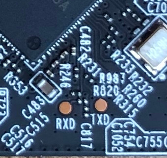
You'll have to take a closer look at the how the traces lead up to the pads labelled RXD and TXD, to see where you might need to bridge any unpopulated current limiting resistors. If the pull-down resistor is unpopulated, do not bridge it, as this may damage your device. Once you've got that figured out, you can solder a wire to these pads and a ground wire to TPGND4 near the ethernet magnetics on the left. Then connect these to a 3.3V serial port adapter to connect to the device's serial port (115200 baud, 8n1). If you haven't soldered a lot before, be very careful not to lift any pads!
The SPI flash chip is on the other side of the board: U31, the 8-pin package labelled "25Q127CSIG".
These are good pictures to put on the wiki page later, by the way 