Maybe use a DM if you don't want to de-rail this topic 
Welp I actually soft-bricked it this time. Tried to flash squashfs-factory under initramfs flashed system. Green light just lits up and stays there. Let's sacrifice this piece to research. I'm going to try to kindly open the chasis and see what's inside.
@svanheule take a look at these pictures while I tear this down.
Edit: Almost impossible to tear it down if I want to put this thing back together. I'm going somewhere with professional tools to safely dismantle it tomorrow.
I've seen the FCC pictures before, but the overview ones are so low-res it's hard to make things out. What you can make out, is that they appear to have gone at the housing with a pair of pliers to get the thing open ![]()
@PolynomialDivision did you ever manage to open the EAP225-Outdoor cleanly?
I have closely examined the housing, I think what it needs is heat, so I can take down plastic parts smoothly without damaging it. This AP supposedly have got IP65 protection as well, I think pair of pliers would pretty much damage the housing.
My man near the beach helped me out how to tear it down. He says he’s got a third eye when he looks at objects 
Edit: Will send high res images of the board when I’m home.
1 Like
Let me now if you need close up shot on any chips.
Edit: I can do a video conference should you need.
1 Like
There it is! On other TP-Link boards, you usually have the following resistors:
- TXD current limiter
- RXD current limiter
- RXD pull-down
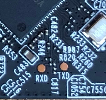
You'll have to take a closer look at the how the traces lead up to the pads labelled RXD and TXD, to see where you might need to bridge any unpopulated current limiting resistors. If the pull-down resistor is unpopulated, do not bridge it, as this may damage your device. Once you've got that figured out, you can solder a wire to these pads and a ground wire to TPGND4 near the ethernet magnetics on the left. Then connect these to a 3.3V serial port adapter to connect to the device's serial port (115200 baud, 8n1). If you haven't soldered a lot before, be very careful not to lift any pads!
The SPI flash chip is on the other side of the board: U31, the 8-pin package labelled "25Q127CSIG".
These are good pictures to put on the wiki page later, by the way
2 Likes
Going to visit my contact in the morning to work on it. Thanks for the detailed information.
Edit: Delayed to Monday, he does not work at the weekends.
Hi PolynomialDivision,
I 'm just new for openwrt. I saw you have tried with EAP225-Outdoor. I have one for this model and found the problem with tp-Link firmware. So, I would like to play with openwrt. It will be appreciated if you kindly advise and guide line me. Thanks in advance.
I've uploaded test builds of my latest patches. Please consult the introductory documentation on OpenWrt and carefully read the install instructions for your device in the commit message.
I have just seen this from the releases page of your repository.
*-sysupgrade.binfor installing from initramfs or a previous install.
I see I have used *-factory.bin from initramfs, it’s surprising it can corrupt the software just by this.
I’m going to take a look at the menuconfig again but is there an option I need to enable to produce sysupgrade binaries as well?
I found an(other) issue with the makefile that resulted in the sysupgrade images not being built. IMAGE_SIZE was not set (so zero), which caused the file size check to fail. I've now fixed this, but if you built with an older version, then you probably had the same issue as me.
Since the factory images don't contain the OpenWrt metadata-blob at the end, the sysupgrade page in LuCI should give you a big warning (and it does when I try) if you try to flash a factory image.
Also, the initramfs is used when you interrupt the bootloader and start that image after downloading it via tftp. Since you only just found the serial port on the EAP225-Outdoor, I doubt you were using an initramfs 
When you flash the factory image via the TP-Link interface, you've got your device set up really. You could flash a sysupgrade image immediately after that to have a more compact flash layout, but that isn't really required.
Will you update the repository to reflect the fix?
That’s nice, I didn’t see that on command line.
I was careless and mistakenly flashed initramfs after flashing factory image ![]() . Then flashed factory image again which broke the thing lol.
. Then flashed factory image again which broke the thing lol.
Interesting. I’ll check this when I recover the device.
I’ll probably have serial console access by tomorrow morning. Plan is to set IP addresses for the PC and the AP to listen at, send the openwrt binary over tftp, erase the old flash and write the new one. I’m going to check if I can find the offsets (I think?) of the flash to erase.
Ah, that explains. I would never try that, but I guess it doesn't make a difference whether you run the initramfs from RAM or from flash in this case.
You should be able to figure it out, but if you can't, have a look at j-d-r's commit for the EAP245-v1 (same flash layout).
I have ![]() (and I linked the releases to the wrong branch
(and I linked the releases to the wrong branch ![]() )
)
Quoting here for ease of access:
To flash OpenWrt from u-boot:
ath> setenv ipaddr XXX.XXX.XXX.XXX (optional 192.168.1.1 by default)
ath> setenv serverip XXX.XXX.XXX.XXX (optional 192.168.1.10 by default)
ath> tftpboot 0x80800000 openwrt-ath79-generic-tplink_eap245-v1-squashfs-sysupgrade.bin
ath> erase 0x9f040000 +$filesize
ath> cp.b $fileaddr 0x9f040000 $filesize
ath> reset
Is the fix included in the latest commit from 3 days ago?
P.S. Should I flash factory or sysupgrade image from serial console?
I've linked my releases (a few posted up) to the correct branch, and they all have IMAGE_SIZE set, so yes.
Once you have serial access, you can try and see which one works ![]()
(It's the sysupgrade image)
Interesting. It wouldn’t produce sysupgrade image on the current state of the repository - tplink_eap2x5 branch - for some reason. I’ll take a look.
Update: Looks like it was a local problem from my side. Everything is fine now.
My contact just did this since I don’t really know or understand what do you mean by unpopulated limiting resistors so I can’t really direct him to do it.
This is the current state of the soldering:
I assume I also need a USB adapter to connect to a PC.
@arinc9 Do you know you can upload images onto the forum directly? If your image host goes down, the images are gone too. Not when you just upload the pictures to the forum.
1 Like