I've tried desoldering the eMMC chip but this board is too thick for my setup, I don't think I'll be able to take it out.
I've probed the surrounding resistors with a multimeter and discovered that there are 8 pull-ups (DAT[0...7]?) on the top side, and a single pull-down resistor on the bottom side (CLK? RST? DS?).
I will try soldering a bodge to the pull-down and attach a scope to it. I've also discovered that unlike you guys my board doesn't have the UART header soldered on, I'll need to add that as well.
Turns out the pin with the pull down resistor is doing absolutely nothing, it's always kept at GND, so pulling it down external does nothing.
In case this might be useful to anybody, the device has a hidden admin page: https://192.168.1.1/#/firmware_upgrade
Also judging by the scope reading the pins on that unpopulated 6-pin header are floating, so probably not connected to anything.
No UART on yours? Interesting. Keep us updated on the bridge. Best of luck.
@jakehemmerle @spol-eff Looks like https://192.168.1.1/cgi/cgi_basic.js will give you CPU temp and memory usage info:
"uptime":"2955184",
"cpuU":"29",
"cpuS":"2",
"cpuI":"65",
"cpuT":"47",
"memT":"1841728",
"memF":"1296136",
"memU":"545592",
"son":"0",
Not sure what we can use "cksum":"b3bfbe171f6392eb23ea20da01adccc9" for tho.
I've located the CLK trace, but pulling it down causes the device to go into a boot loop instead of EDL mode.
This is a bootlog with a shorted CLK:
Format: Log Type - Time(microsec) - Message - Optional Info
Log Type: B - Since Boot(Power On Reset),  D - Delta,  S - Statistic
S - QC_IMAGE_VERSION_STRING=BOOT.BF.3.3.1-00163
S - IMAGE_VARIANT_STRING=HAASANAZA
S - OEM_IMAGE_VERSION_STRING=CRM
S - Boot Config, 0x000002e3
B -       201 - PBL, Start
B -      2735 - bootable_media_detect_entry, Start
B -     35300 - bootable_media_detect_success, Start
B -     35305 - elf_loader_entry, Start
B -     36709 - auth_hash_seg_entry, Start
B -     74772 - auth_hash_seg_exit, Start
B -     89388 - elf_segs_hash_verify_entry, Start
B -    152021 - PBL, End
B -    242505 - SBL1, Start
B -    319213 - GCC [RstStat:0x10, RstDbg:0x600000] WDog Stat : 0x4
B -         0 - Debug Log
B -         0 - GCC_RST=0:r2=925984C0:r3=F79634A2:r4=42DD5153:r5=2D97845:r6=F154A30E:r7=F9E02F0B:r8=10CC1657:r9=4600E418:r10=AD1803B3:r11=13E859F0:r12=C9B87318:r13=3AD58A30:r14=77C7D370:r15=5F1E4F75:r16=0:r17=9832D580:r18=7F346312:r19=9485EDC5:r20=C55A1ED5:r21=D5E38610:r22=B90771AA:r23=D145B632:r24=408403C0:r25=41823730:r26=DE773494:r27=5D5B0250:r28=D411130:r29=DE321955:r30=78D4240:r31=FD8B1F41:r32=0:r33=0:r34=921713DE:r35=70201600:r36=0:r37=0:r38=0:r39=0:r40=0:
B -    396683 - pm_device_init, Start
B -    580903 - PM_SET_VAL:Skip
D -    183671 - pm_device_init, Delta
B -    583312 - pm_driver_init, Start
D -      5215 - pm_driver_init, Delta
B -    589534 - clock_init, Start
D -      2165 - clock_init, Delta
B -    593682 - boot_flash_init, Start
D -      4331 - boot_flash_init, Delta
B -    601704 - boot_config_data_table_init, Start
B -    605333 - CDT Partition Loading Failed. Trying Alternate CDT Partition...
Do you have a picture where CLK is? I can do a test on my board as well.

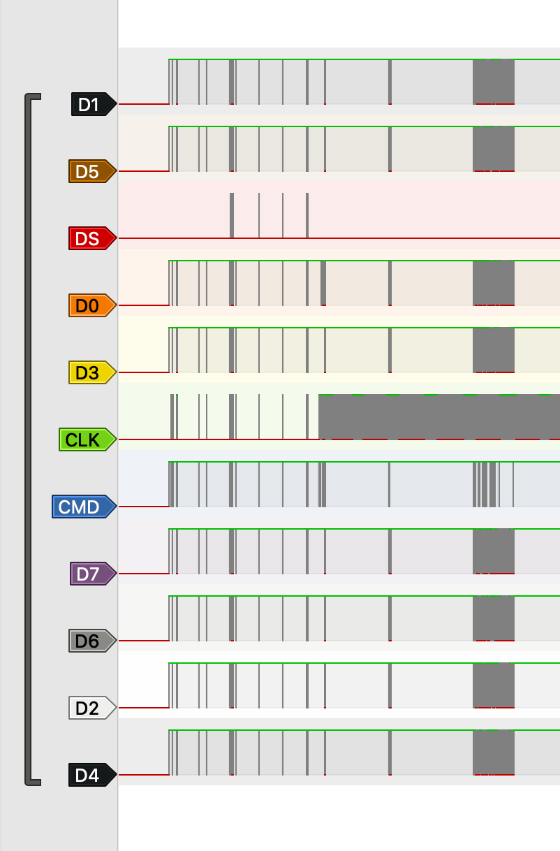
This is my best guess, I'm certain that CLK and CMD are correct (was able to decode them with a logic analyzer), D0 is still up in the air as I wasn't yet able to dump the chip.
There's also a RST on the bottom, but to get to get you have to grind down a via and solder to it. I can send a picture of it later.
2 Likes
I don't think it's possible to dump the chip without desoldering. The CMD line seems to be always strongly pulled up when powered externally.
In cases like this it's sometimes possible to use internal power, and you keep the CPU from booting by shorting the crystal pins, but in this router the clock is managed by PMIC. You could in theory disable the PMIC, but PMIC is also managing 1.8V power supply, using the same crystal, so no crystal = no power.
We need somebody to desolder the chip and dump it. But as I said before, the board is extremely thick, with many layers and huge ground planes, so you need very good preheating, which I don't have.
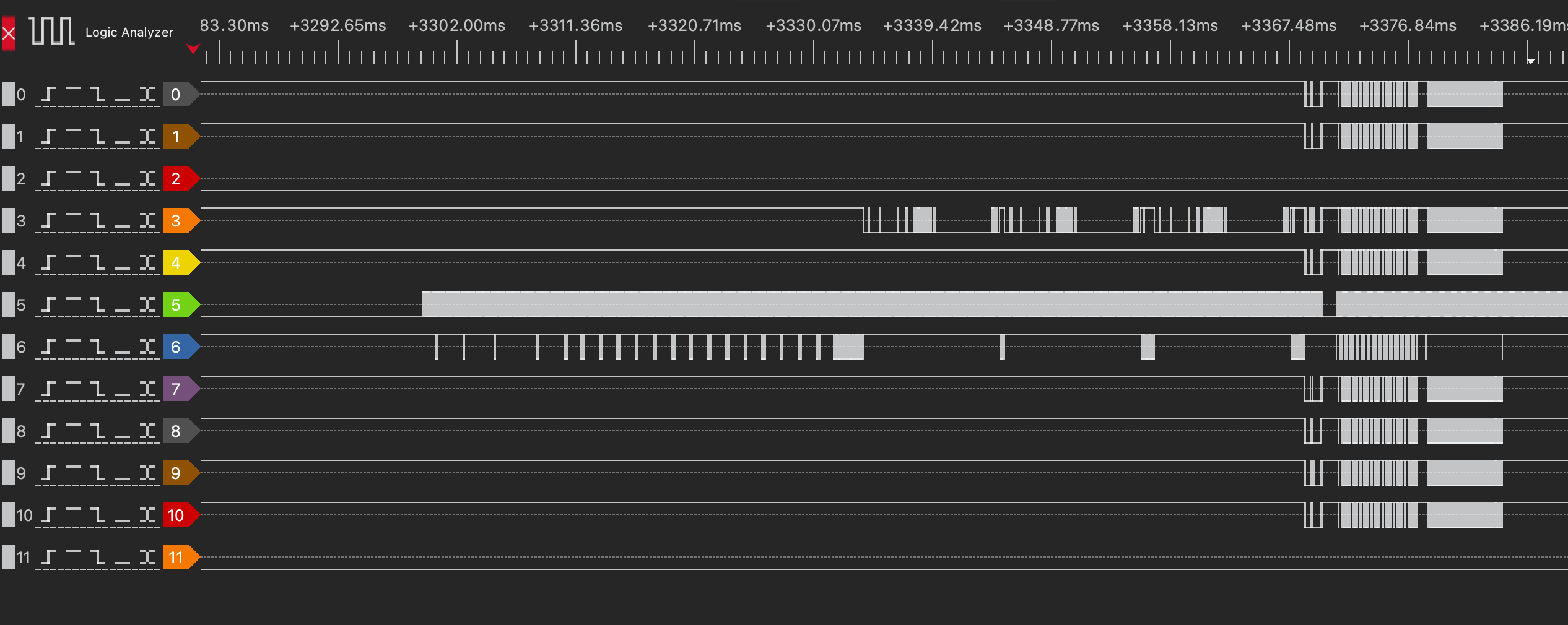
PM me if you'd like a logic analyzer dump of the boot process, it probably has enough information to reconstruct the u-boot and kernel binaries if you're smart enough (I'm not). Then after the kernel boots it switches the eMMC to HS mode and my logic analyzer doesn't have enough sample rate to capture that.
some progress with decoding the logic analyzer dump
EDIT: here are labels for all the 11 traces, in case somebody finds it useful:
and a piece of Swift code I used to find the correct permutation:
import Foundation
import Algorithms

let names = (0...7).map { "D\($0)" }
let files = try names.map { try Data(contentsOf: URL(filePath: "/Users/user/Downloads/\($0)_csd.bin")) }
let bits = files.map { Array($0.map { $0 == 0x1 }.dropFirst().prefix(512)) }

var permutations = Array(Array(names.enumerated()).permutations())

func checkPermutation(_ p: [(offset: Int, element: String)],
                      range: ClosedRange<Int>,
                      pattern: [UInt8]) -> Bool {
  var samples = [UInt8](repeating: 0x0, count: range.count)

  for index in range {
    for laneIndex in p.indices {
      let lane = p[laneIndex]
      let laneBit = UInt8(bits[lane.offset][index] ? 0x1 : 0x0)
      let shiftedBit = laneBit << UInt8(laneIndex)

      // this might need endianness swap when running on x86, I'm on M1 so I didn't bother
      samples[index - range.lowerBound] |= shiftedBit
    }
  }

  return samples == pattern
}

func narrow(range: ClosedRange<Int>, pattern: [UInt8]) {
  var newPermutations = type(of: permutations).init()

  for p in permutations {
    if checkPermutation(p, range: range, pattern: pattern) {
      newPermutations.append(p)
    }
  }

  permutations = newPermutations
}

narrow(range: 16...16, pattern: [0x09])
narrow(range: 17...17, pattern: [0x03])
narrow(range: 18...21, pattern: [0x00, 0x00, 0x76, 0x00])
narrow(range: 60...60, pattern: [0x0a])
narrow(range: 63...63, pattern: [0x01])
narrow(range: 130...130, pattern: [0x01])
narrow(range: 157...159, pattern: [0xd8, 0x01, 0x00])
narrow(range: 160...160, pattern: [0x07])
narrow(range: 166...166, pattern: [0x05])
narrow(range: 167...167, pattern: [0x1f])

for permutation in permutations {
  print(permutation.map { $0.element })
}
this relies on capturing 8x 513 byte data blocks sent after CMD8 (SEND_IF_COND): Send interface condition to card, and then taking values of Extended CSD Register from datasheet and putting them into the narrow function until you're left with a single permutation.
2 Likes
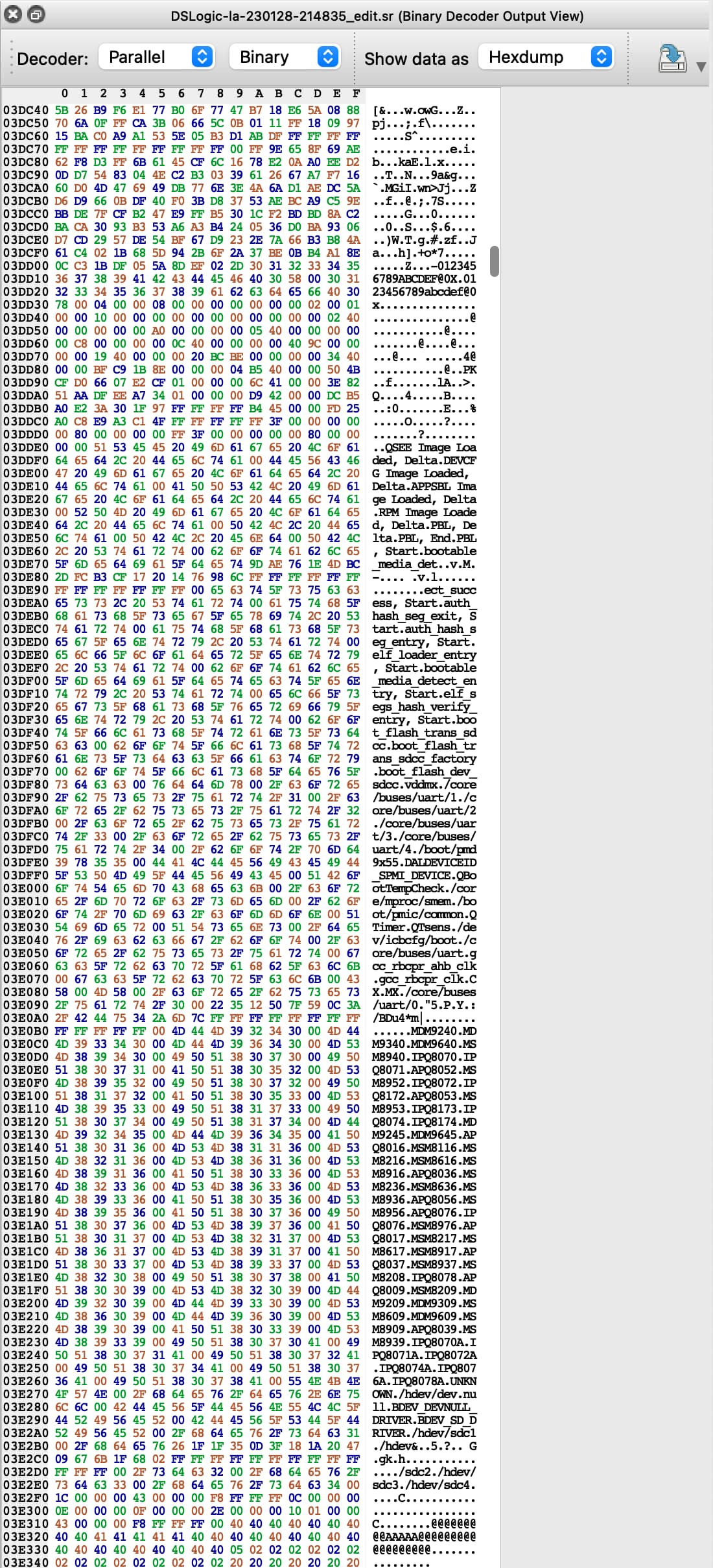
Alright I've managed to reconstruct parts of the eMMC from the dump, but it's very corrupted so not very useful.
Here's one interesting string I've found inside (PI redacted):
5gSåadminpass=*****
baseMAC=**:**:**:**:**:**
baudrate=115200
bootargs=console=ttyMSM0,115200n8 vmalloc=900M  cnss2.bdf_pci0=0xa4
bootcmd=bootipq
ethact=eth0
ethaddr=**:**:**:**:**:**
fdt_high=0x4A400000
fdtcontroladdr=4a972e50
fileaddr=44000000
filesize=1c8
flash_type=5
ipaddr=192.168.1.1
machid=8010012
macno=7
model=CR1000A
netmask=255.255.255.0
serialno=************
serverip=192.168.1.100
soc_hw_version=200d0200
soc_version_major=2
soc_version_minor=0
ssid=Verizon_******
This is the the u-boot environment. Nothing of particular interest here for the time being.
Is that possible you can extract encrypt key for the config and then try to decrypt config modify TR069 address to active SSH? I have an ACS server running and tried to replace my ACS server address to the TR069 server IP with no luck, but if we can modify config with acs IP and port that should be fairly easy.
I thought so too, but this is the most interesting string I got out of the dump so far. It at least hints at TFTP being potentially used to do something.
This was the article I followed: https://gorgias.me/2017/09/01/FIOS-G1100-获取ROOT权限/
The only different is that G1100 model already has config decrypted but CR1000A does not. The SSH active part should be same.
No I can't, the device is switching to the HS400 eMMC mode when loading the root fs, and my logic analyzer isn't good enough to capture that a signal that fast.
Also FWIW, the other unpopulated 6-pin header (JT2), is wired to the unpopulated BLE module's UART lines, which in turns is wired to the CPU through a some kind of IC on underneath the header, also unpopulated (level shifter maybe)?
I tried soldering bodges to them, but nothing seems to be happening there.
If you’ve identified the eMMC data pins you could try grounding them at boot and seeing if it goes into recovery mode