My devices are currently in production, so even if I wanted to break them open, I can't easily replace them right now.
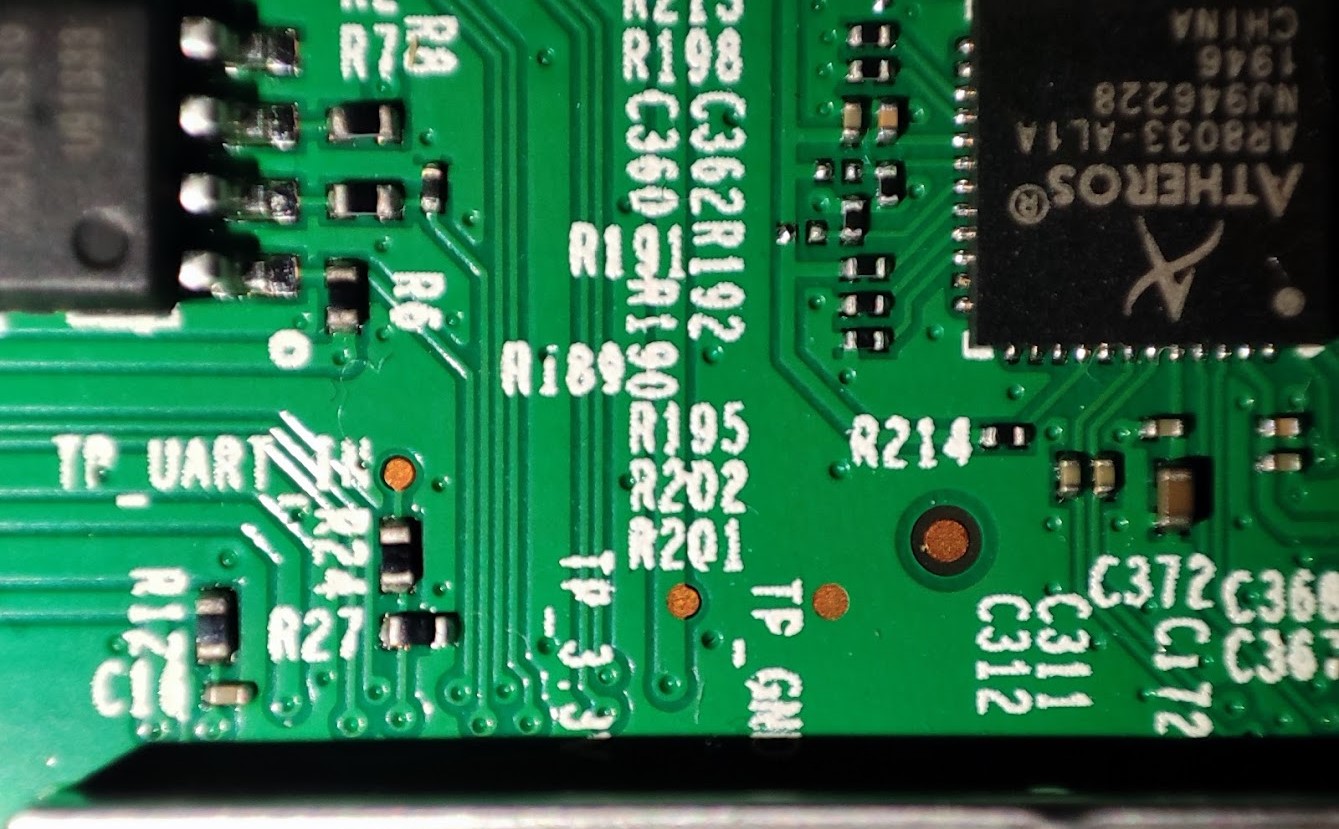
But he says in his very first post here that Uart/serial is exposed on three test points. I can only wonder if that means that your TP_3.3V is the UART_OUT pin. I'm just not sure about that.
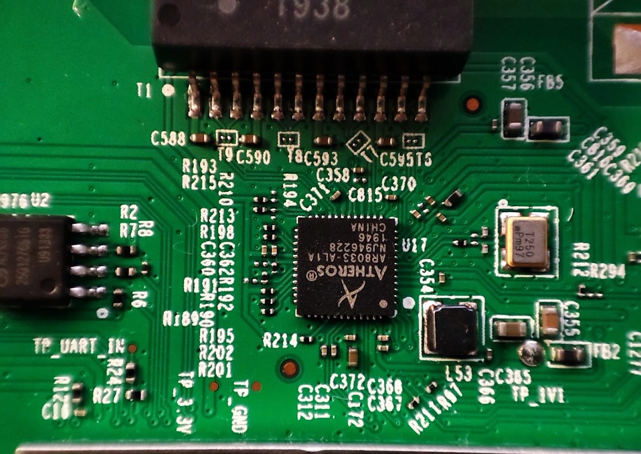
Maybe post a photo with good quality so we can actually see what is printed on the board and I'll have a look.
Apart from that the serial connection of such devices usually consists of 4 pins: 3.3V, TX, RX and GND.
You definitely need GND so the device and your PC share a common ground so both ends have a reference to even know what 5V is for instance.
You definitely DON'T want to touch the 3.3V because that can lead to your PC damaging the device or vise versa. The PC has its own power supply and so does the device.
RX (your TP_UART_IN) is used to receive commands from your serial console on your PC.
TX is used to transmit whatever the device wants to print to your serial console. And without that you're flying blind.
So either the TP_3.3V pin is the TX pin or we have to find that first.
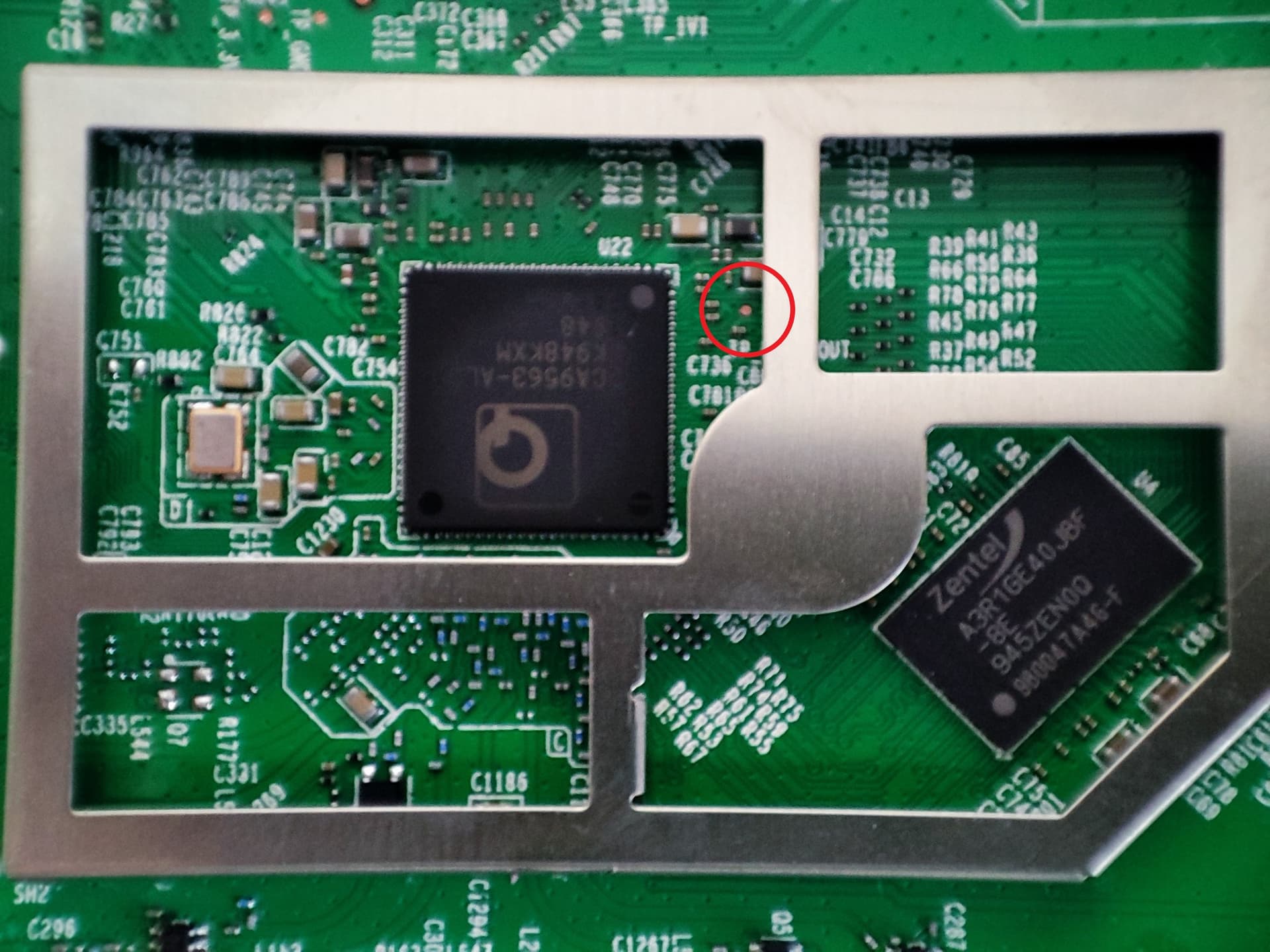
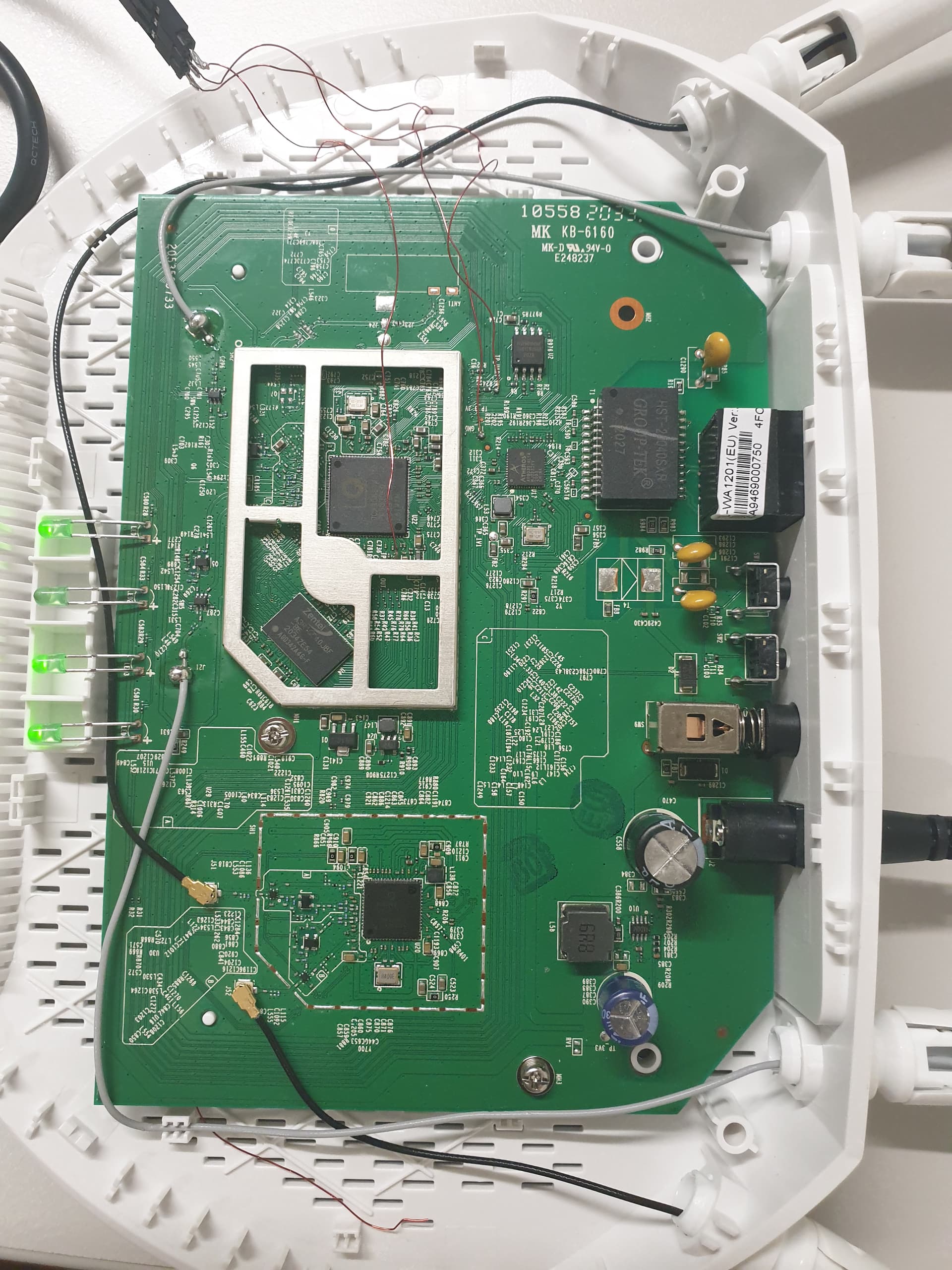
I am struggling a bit for pics to come out well, perhaps these help?
TBH Even if we identify the correct points I doubt my soldering skills are up to it, but perhaps this will help someone else.
Going back to the "blind" TFTP, I did have a look at the traffic with wireshark and it does seem to be transferring an image but then not "doing" anything with it. Perhaps these images need to be trimmed?
Having said that, the image is going in 2-3 seconds which seems suspiciously fast to me...?
Trying the TP-Link firmware or any of the openwrt images doesn't work.
The bootloader might load the image into RAM just fine, but you don't know what it does after that. It might be checking the image for some checksum or there might be some other problem and that will only present itself via the serial console.
If those are the only three pads you see then you could try TP_3.3V with a multimeter against TP_GND and see if the voltage fluctuates. If it does then that might be TX. But I would rather wait for bluewww to tell you what is what.
Yes, that's what I meant. If TP_3.3V was the actual Vcc pin then it would read 3.3V constantly. Since you checked and it doesn't that means that it's the TX pin of the SoC and you can connect that to RX of your TTL usb dongle.
Now knowing what connector of the usb dongle needs to be connected to which pad, you can use that together with a serial monitor application (like putty if you're using Windows) and can see what the bootloader spits out.
Guess I was wrong with my assumption then. Just strange that the Vcc pin only reads 2.9V. I would have imagined that this would only happen because the multimeter doesn't display the fast change of voltages while characters are sent (if it was the TX pin).
About your bricked device:
Here is a similar bricked TP-Link device after trying to flash the stock firmware: EAP245 (US) V3 - Soft bricked
Might be the same reason your device is now soft-bricked.
But you should of course first get serial console access so you can see what the problem actually is.
About flashing the stock firmware:
I didn't know that either until now because I have no desire to go back to stock on my devices but it seems that if you want to do that then you have to compile the tplink-safeloader.c and convert the stock firmware to a sysupgrade firmware as talked about in this reply: Adding OpenWrt support for TP-Link EAP245 - #145 by svanheule
That of course only works if you have a running OpenWrt firmware on the device. So first get access to the serial console to see what error it spits out.
As a soldering beginner, you can easily (but inadvertently) combine the one with the other.
Rule #1 for beginners: Don't overheat the board by repeatedly holding the soldering iron for extended periods of time onto the board. Soldering a wire to the board should not require more than 5sec (!) of the soldering iron in contact to the board, per wire.
He used coated copper wire for micro soldering. But if you're careful you might get away with jumper wires like I used on my deco m4: https://imgur.com/a/gK1CHMb
Just don't heat up anything for too long like @tmomas said.
About your step 2: Just make sure that the signaling isn't above 3.3V or else you risk permanently damaging your device. If I was in your shoes I would order a 3.3V dongle like discussed on this page: https://openwrt.org/docs/techref/hardware/port.serial.cables
Hot glue is your friend, glue the cables to empty places on the board to relieve the stress of your soldering points. Masking tape can also come in handy.
I managed as well to install on my new WA1201 OpenWRT ( big thanks @bluewww great work!).
The main reason for installing OpenWRT was to have the openVPN client as I need an AP that runs a VPN.
However I see that the openVPN is not available in LuCI. Adding the offical openvpn-openssl packages does not work as this is a custom build.
I tried to build it myself but being new to this stuff I could find any sources related to openVPN on the git shared.
Can anyone help or at least clarify it is possible to have it?