Yeah like Adrian said in the PR, have another partition between firmware and art, maybe called "cert", and also make it read-only
Absolutely, i'll fix that later today when i get the time.
And thank you for your help, i can finally throw my old Netgear R7000 away and get coverage in the whole house.
or sell it for cheap, so as to not be wasteful ![]()
2 Likes
True!
If you got the time i would appreciate it very much if you can help out with the git stuff. It's very much new territory for me as i normally work with technology from the middle ages (PLC-programming with file check in/out).
How would you steer this further?
Thank you!
1 Like
hey guys
when do you think you will be able to make the git commit?
cant wait to try it out on my unit
It's almost complete. I've just started working again after a few months of parental leave so i cannot spend as much time on it as i wanted.
I'm gonna test a change to the internal WDT tonight and then its probably ready. The build i'm having on one of my units now with all Img-partitions and the big FS-one merged into one "firmware"-one is going strong. Up for 5 days now without any errors or warnings.
If you want you can clone from this and try it out:
I have one unit up and running now with the latest changes. I did a clean git-clone and used a fresh unit following the commited "install instructions". So far it's running without any issues.
I can report back tomorrow as well if you want.
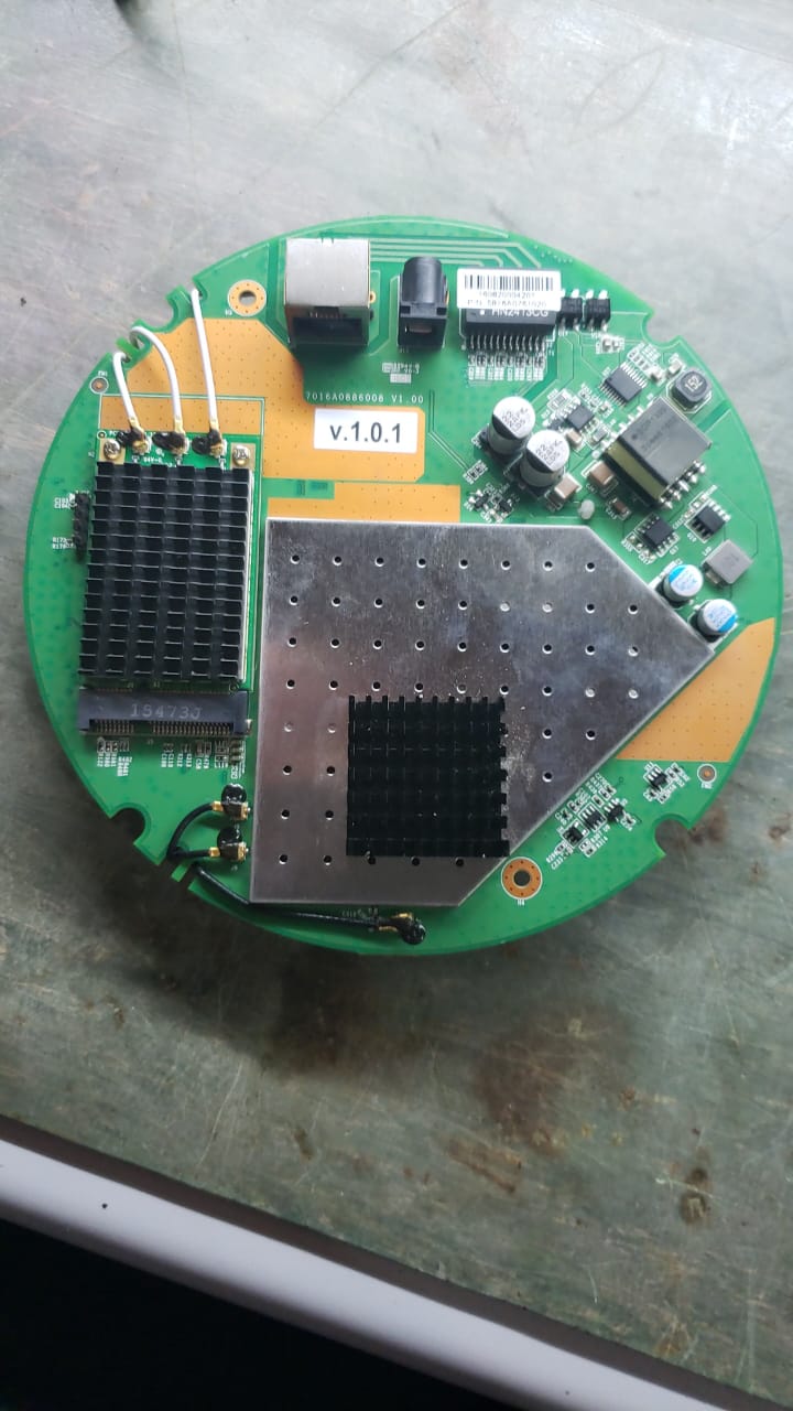
Hi there! I´m new around here and bumped with this thread trying to found a functional firmware to a bunch of Watchguard AP300 that´s already out of support. From my tear down of AP300 It use exactly the same board as this extreme: 7016A0886008 v1.00 (With a label with v1.0.1)
There is some binary available to try it on these devices?
1 Like

@akornow you are welcome to copy his branch and adjust it as you need, then build your own image
generic guide for setting up the build system
https://openwrt.org/docs/guide-developer/quickstart-build-images
after cloning master
start from master
git checkout master
make a new branch
git checkout -b ap300
pull his commits
git pull https://github.com/albinhe/openwrt.git master
revert the commits to staging (he still has 4 commits so do this 4 times)
git reset --soft HEAD^
see all the files with changes
git status
git diff
see commits in order (if you are unsure where HEAD is)
git log
you should first have serial console access and use tftpboot and bootm commands to load the initramfs-kernel.bin for testing, this will not affect the flash memory. While you have the initramfs-kernel.bin booted you can also backup all partitions. Building with LuCI helps since there is a simple way to backup partitions with LuCI in the master branch.
Be careful with this assumpton, the board can be exactly the same, but the chips can be different
for example a small detail: I see 3 antenna wires from the SOC. This tells me it is a QCA9558 instead of a QCA9557 (this is not a very important difference, as they use the same DTS values from the qca955x.dtsi file)
however for the PCI card (white antenna wires) It might be a completely different wifi chip. You should carefully remove the shields and record all the chip models including the flash chip to be sure. It is like a cap and you can pry it off carefully all the way around with a very small screwdriver, being careful not to hit small components.
@mpratt14 Thanks for your prompt response!
Will try to connect pci-express wifi board to a Laptop to see which chipset it detects.
1 Like
If you are uncomfortable with removing shields then you don't have to do anything
the model can usually be discovered by the vendor / device ID
you see this in the kernel log when you will boot initramfs-kernel.bin
Example:
[ 1.225241] pci 0000:00:00.0: [168c:003c] type 00 class 0x028000
here is a list that roughly compares device ID to model for qualcomm wifi chips
Thanks again!
Vendor firmware is locked because it is managed by a GWC, I can't logon it to upload custom firmware.
Just in case... Do you have pinout of serial interface on it? I found GND, but not sure RX & TX.
I do believe that 2 is GND, 3 is TX and 4 is RX, but I´m just get garbage while booting. Trying using putty, 115200 8n1
Best Regards
Serial console is the only way to upload initramfs-kernel.bin without changing flash data, so you have to figure it out anyway
Most important is to figure out which pin is 3V power and which pin is GND
Never use the 3V power pin. I like to bend it so that I never forget which one it is
The order of TX and RX and GND can be guessed safely
but the 3V power pin must be known before connecting
If you have garbage output there is 2 possibilities:
- you connected GND to something else
- wrong baudrate
Edit: there is another possibility...
Try to connect only GND and RX (reading output only, no input)
it is possible that the input pin is tied to ground, in that case a resistor must be removed for TX to work
I have added a board that is almost exactly the same, here is the part where I talk about serial access
  the RX line on the board for UART is shorted to ground by resistor R176
  therefore it must be removed to use the console
  but it is not necessary to remove to view boot log
  optionally, R175 can be replaced with a solder bridge short

  the resistors R175 and R176 are next to the UART pinout at JP1
(when I say RX in this commit message, I mean the board's perspective, which for you is TX)
before removing any resistor, you should verify that this is the case with a multimeter in continuous mode
also like I said, if you have only GND and RX connected, the output is clean, but with all 3 connected the output is dirty, this is the symptom
Pin 3 seems to be TX. R175 is not installed here and as i can measure, one of it lead is grounded and another is connected to R176. Another R176 lead is connected to pin 4 and is 56R. Seems to be RX (all of them are from AP perspective).
Trying using only GND and Pin3 doesn't clean text.
Didn't found any other near connection to junction between R175 an R176.
GND -----{R175(Missing here)}------{R176(56R)}------Pin4
Your best guess is... To remove R176 or short R175?

before doing anything to the resistors we need to be sure
connect to serial with only 2 pins, GND and RX (reading)
you should be able to get clean output without TX (writing)
I already did it... Just GND and RX doesn't changed anything...
removing the resistor will fix your TX but your RX should still be possible...and still a concern...
be absolutely sure that the resistor is connected to ground and one of the pins
remove it if this is true
Yeah... Actually seems that these 2 resistors are related to TX. None of them are connected to RX. Will try to remove it just in case...