Add support for Datto L8, E24v3, E48 switches

I was digging around the firmware and GPL source code to try and find out how the fans are initialised. modsqfs/lib/modules/2.6.19/kernel/drivers/net/switch/board/board.ko seems likely as it contains some fan-related strings:

$ strings ./modsqfs/lib/modules/2.6.19/kernel/drivers/net/switch/board/board.ko | grep -i fan
Detect fan failed.
Fan has recovered

But this module isn’t GPL licensed and wasn’t included in the Datto GPL archive:

filename:       ./modsqfs/lib/modules/2.6.19/kernel/drivers/net/switch/board/board.ko
license:        Realtek Semiconductor Corp.
description:    Switch Board Vendor Module
depends:        ski,rtcore,rtk
vermagic:       2.6.19 preempt mod_unload MIPS32_R1 32BIT

Not that helpful, but while I was digging around the source code I found comments from Senao:

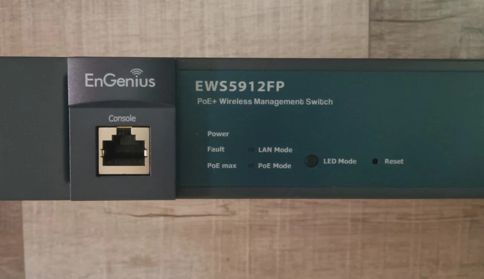
Speculation: It looks like the EnGenius EWS5912FP is the same Realtek reference design as the OMS 8/Datto E8. They have the same LEDs and LED Mode/reset button placement, and the same port layout. (Photos are from eBay listings)

The EnGenius EGS7228P is probably an RTL8382M_8218B, and the EnGenius EGS7252FP is probably RT8393M.

All this is pure speculation, I don’t own (and don’t plan to buy) those models, but just thought I’d leave it here for the next person to run across it.

I have a photo of the EnGenius EWS5912FP on the entry at WikiDevi and it does appear very similar. The boards do have different Board ID but they are from the same manufacturer.

1 Like

Support for the Datto L8 is basically done: POE is working, LEDs are working, reset button is working. I need to clean it up before I submit a PR though. You can even install OpenWrt from the stock OMS web admin interface, no need to open it up and connect UART:

Which brings me to a question that maybe @svanheule can answer. There is an “LED Mode” button on the switch that in the stock firmware toggles between the Ethernet port left LED showing link status or POE status. The button also seems to exist on two other rtl838x switches: rtl83xx_panasonic_mxxeg-pn28xx0k.dtsi and rtl8380_engenius_ews2910p.dtsi

With OpenWrt flashed, pressing the “LED Mode” button does absolutely nothing. I can’t find anything in target/linux/realtek/base-files that suggests there is any functionality tied to this button in OpenWrt. Is this button supposed to do something in OpenWrt and I’ve just missed configuring it on the Datto L8?

1 Like

The BTN_0 key is not in any standard scripts and needs to be wired up by the user.

That being said, we don't really support port LEDs via the hardware peripheral at the moment on RTL838x. I've picked up my old patches to support that recently (with modern netdev offloading), but I'm pretty busy with other things too.

1 Like

Thanks for clarifying. A follow up question while you’re here.

Datto switches have an A/B firmware layout:

[    0.747669] Creating 7 MTD partitions on "spi0.0":
[    0.753272] 0x000000000000-0x000000080000 : "u-boot"
[    0.765720] 0x000000080000-0x000000090000 : "u-boot-env"
[    0.776410] 0x000000090000-0x0000000b0000 : "sysinfo"
[    0.786890] 0x0000000a0000-0x0000004a0000 : "cfg"
[    0.796961] 0x0000004a0000-0x0000005a0000 : "log"
[    0.806910] 0x0000005a0000-0x0000012d0000 : "firmware"
[    0.818034] 2 uimage-fw partitions found on MTD device firmware
[    0.824849] Creating 2 MTD partitions on "firmware":
[    0.830461] 0x000000000000-0x0000003d0000 : "kernel"
[    0.840305] 0x0000003d0000-0x000000d30000 : "rootfs"
[    0.850508] mtd: setting mtd7 (rootfs) as root device
[    0.856465] 1 squashfs-split partitions found on MTD device rootfs
[    0.863593] 0x0000005f0000-0x000000d30000 : "rootfs_data"
[    0.874501] 0x0000012d0000-0x000002000000 : "firmware2"

U-Boot stores the partition offsets of firmware and firmware2 in variables which could be changed by upgrade.sh during a sysupgrade to gain more space:

flashoffset_linux=0x5a0000
flashoffset_linux2=0x12d0000
ssize_linux=0xd30000
ssize_linux2=0xd30000

The initial image uploaded through the web UI would need to fit within the stock size of 0xd30000, as we don’t have a way to change the U-Boot env from the stock firmware.

Is there some way to have OpenWrt generate an additional factory image that can fit within 0xd30000 for flashing? Then the user could SSH to the initramfs image, run sysupgrade and benefit from merging firmware and firmware2 partitions.

The Zyxel GS1900 images have a similar check, so you could check those recipes. The check ensures the initramfs (factory) image stays within the size of the original partition, while the sysupgrade image can be the size of the merged firmware partitions.

I have both the L8 and the OpenMesh S8-L which are essentially the same hardware. Let me know when you have a PR ready and I can test on both devices and add a tested by.

1 Like

Easy root shell in the Datto firmware:

Interrupt U-Boot by typing pac, then:

sf read $(freemem) $(flashoffset_linux) $(ssize_linux)
setenv bootargs console=ttyS0,115200 mem=256M rdinit=/bin/sh
bootm $(freemem)

When you’re dropped to the shell early in boot, run the following:

rm /bin/cli
/etc/rc

The switch will continue booting but instead of the useless Datto cli, you’ll have a root shell.

There is a Realtek diag binary located in /sqfs/bin/diag:

RTK.0>  ext-gpio dump dev 0 
    Device Status: Ready
    Device State: Enabled

    ==================================
     GPIO# | Sel. | Direction | Value 
    ==================================
       00  | GPIO |    OUT    |  1
       01  | GPIO |    OUT    |  1
       02  | GPIO |    OUT    |  1
       03  | GPIO |    OUT    |  0
       04  | GPIO |    OUT    |  1
       05  | GPIO |    OUT    |  0
       06  | GPIO |    OUT    |  0
       07  | GPIO |    OUT    |  0
       08  | GPIO |    OUT    |  0
       09  | GPIO |    OUT    |  0
       10  | GPIO |    OUT    |  0
       11  | GPIO |     IN    |  1
       12  | GPIO |     IN    |  1
       13  | GPIO |    OUT    |  0
       14  | GPIO |     IN    |  1

--More--
       15  | GPIO |    OUT    |  0
       16  | GPIO |    OUT    |  0
       17  | GPIO |    OUT    |  0
       18  | GPIO |    OUT    |  0
       19  | GPIO |    OUT    |  0
       20  | GPIO |    OUT    |  0
       21  | GPIO |     IN    |  1
       22  | GPIO |    OUT    |  0
       23  | GPIO |     IN    |  1
       24  | GPIO |    OUT    |  0
       25  | GPIO |     IN    |  1
       26  | GPIO |    OUT    |  0
       27  | GPIO |     IN    |  1
       28  | GPIO |     IN    |  1
       29  | GPIO |    OUT    |  0
       30  | GPIO |    OUT    |  0
       31  | GPIO |    OUT    |  0
       32  | GPIO |    OUT    |  0
       33  | GPIO |    OUT    |  0
       34  | GPIO |    OUT    |  0

--More--
       35  | GPIO |    OUT    |  0
       36  | GPIO |    OUT    |  0

Unfortunately, this output doesn’t help me much and doesn’t seem to change at all if I press the “LED Mode” button on the switch. Pressing the reset button reboots the switch. I also tried reading the internal and rtl8231 GPIO from U-Boot:

switch# # rtk ext-pinGet 0
pin0:   0
switch# # rtk pinGet 0
pin0:   0

Going through all the internal and external GPIO pins, I can’t see any difference if I read them (for the initial value), hold down the “LED Mode” or reset button, and read them again.

@svanheule or @RaylynnKnight you have a history with these platforms. How can I go about determining the reset/LED Mode button GPIOs? Everything I’ve tried thus far has been useless.


There is also a dump register command in diag

RTK.0> diag dump register 
MAX_REG_IDX = 693


REG_idx(0000) bit_offset = 0: 
Register 0x0 : 0x00000000

REG_idx(0001) bit_offset = 0: 
Register 0x4 : 0x003fff21

The output is very verbose, too long to post here. Does anyone want to take a look? Let me know in a DM how I should get the file to you.

I typically try to trace where the button leads to with a multimeter, if the vendor firmware doesn't provide sufficient info. The SoC GPIOs don't automatically mux to their GPIO function, and only GPIO1 doesn't have an alternative function: https://svanheule.net/switches/gpio_control
You'll have to enable the right pin configs in the devicetree if you want to mux everything to GPIO.

If you have all the GPIO controllers up and running, perhaps you could use gpiomon?

Do you know how GPIO works in U-Boot on these platforms?

I would expect rtk pinGet (internal GPIO) or rtk ext-pinGet (8231 GPIO) commands in U-Boot to show something when pressing the reset button, but that doesn’t seem to be the case.

Unfortunately the E24v3 and E48 are using rtl839x chips, so they’re BGA and probing the button →pin isn’t really an option unless I want to take the destructive route.

Simply probe them from user space. I usually use a variation of these scripts:

Thanks, I’ve tried that already. Nothing happened when I pressed the LED Mode/Reset buttons. I’m guessing that was because the pins were not muxed to GPIO in the device tree. I’ll take a look at assigning them to GPIO and try again.

1 Like

E8, E24, and E48 all have core functionality working now:

  • Copper ports
  • POE
  • Fans
  • LEDs

WIP:

  • E24/E48: SFP/SFP+ ports
  • E8: copper ports lan9, lan10, SFP ports

Branch is here for anyone wanting to experiment: https://github.com/halmartin/openwrt/tree/rtl83xx-datto

You may now add a “Tested by rayknight@me.com” on Datto L8. Will be testing an OpenMesh S8-L soon.

I have the Open Mesh OM S8 which appears to be identical to the datto E8, so will test when I have time. Thanks for your work on these!

1 Like

Will test your branch on the E24 this weekend

I can share pre-built images with you. I’ll PM you.

Fantastic work @hmartin

Tested on Datto E24v3. Confirmed that everything you noted is working.

Fans are controllable by PWM by writing values as needed to /sys/class/hwmon/hwmon1/pwm1 as needed so they don't need to run at full blast constantly (lowest safe value seems to be around 100 during some stress testing)

POE works once flashed with sysupgrade image however ubus call poe info does not report correct POE stats. I had two powered devices running as expected but the consumption still showed 0 and the ports were listed as "unknown" even though they were supplying power.

Minor: The power LED is inverted. It flashes during boot but turns off after boot completes. /sys/devices/platform/leds/leds/green:sys/brightness (also found at /sys/class/leds/green:sys/brightness) is set to 1 at boot but needs to be 0 to be on solidly.

On my unit anything below 255 seems to shut off the fans completely. Are you sure they're still running?

If it actually works on your unit, then we should set up a fan curve instead, the lm63 has 8 temperature set points and can automatically scale the fan speed based on temperature sensor measurements.

@svanheule how do you normally probe the SFP SCL/SDA lines? Do you have something like this? https://codeberg.org/jonasjelonek/SFP_breakout/

Also, the E8 has an 8214FC that has 2 copper and 2 SFP ports, but it looks like all other switches supported by OpenWrt have only SFP ports. In macros.dtsi I see EXTERNAL_SFP_PHY and EXTERNAL_SFP_PHY_FULL but nothing for copper ports attached to an external PHY. Should I define a new macro or how do I approach this? Or is this just another PHY_C22?